2007 Spring Semester Engineering
Senior Design Project
Here is my senior design project for
my engineering degree at the University of Central Florida. I chose to do a solo
project to avoid budget or time issues that may be associated with group
projects. My project may have been a little on the expensive side, but I built
it with the skills I acquired during undergrad, which was the whole purpose of
the build.
Here is my entire project in .pdf
form for you to view.
There are also videos of the bike
taken at different stages after the initial drive:
Front Yard Video
Weekend
Test
Build Slideshow
Sometime in 2001 I got a Dixie
Chopper lawnmower tire and bought a rim with a centered mounting flange to fit
it. Not knowing what to do with it at first, it sat around for a year until my
dad suggested using it on a mini-chopper project. I thought about it somewhat
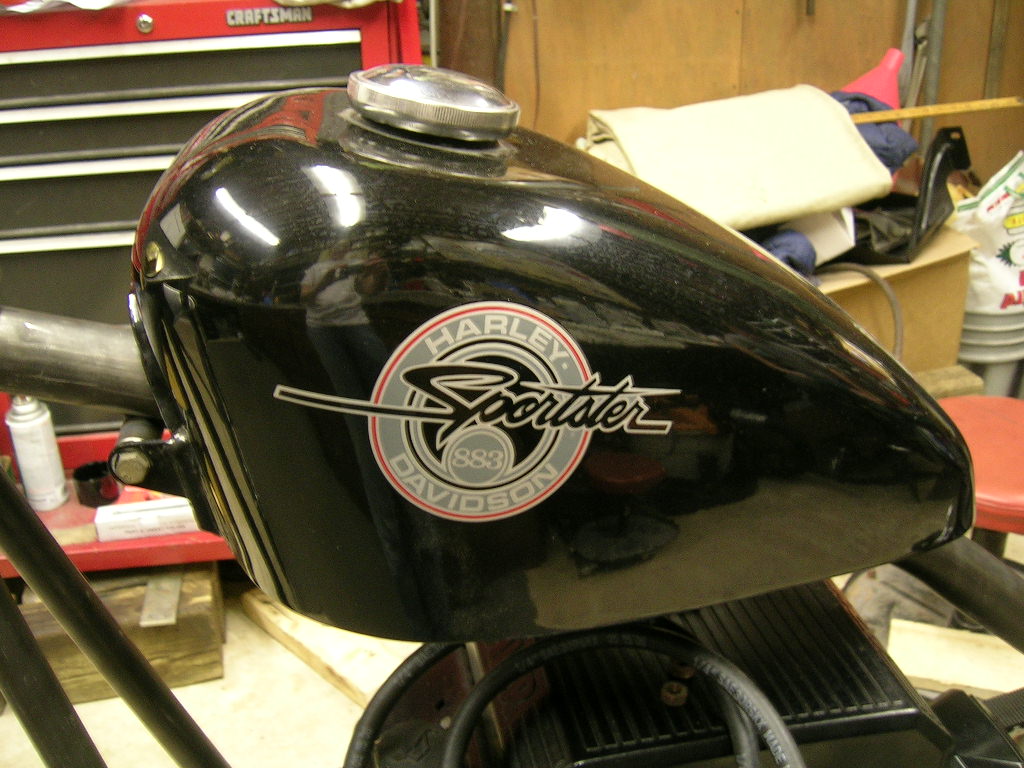
and then began collecting parts on eBay (Sportster gas tank, Comet
needle-bearing centrifugal clutch, Bendix ATV drum brake, etc.). With college
and my girlfriend requiring more time, the mini-chopper project was set on the
back burner (more like it fell off the stove and landed in the dust on the floor
behind the oven haha). I always knew I wanted more hp than what a 5hp or even
modified 5hp B&S could offer. I even wondered if an 8hp B&S I/C engine with
Kehin carb and no governor would work. Then Northern had a price drop on the
Honda GX-390 13hp engine and I thought this would be perfect. Another year went
by and I realized people were putting Vanguard engines in Cushman motor scooters
and doing in excess of 70mph! So it was in that aspect I knew I needed a V-Twin!
And luckily I had one sitting on my go kart from a few years earlier.
Fast forward to January of 2007. I was graduating college and needed a
mechanical type project to design/build in order to pass the senior design
project requirement. I really did not like the projects other students were
contemplating, so I decided I was going to go solo on my project. This was
allowed and I realized if I ever wanted to build another minibike this would be
the way and how to do it.
So the months of January and February were spent researching and designing a
chopper bike. I realized there were several goals I wanted accomplished that I
have yet to see another individual create or use in their mini-project. These
include:
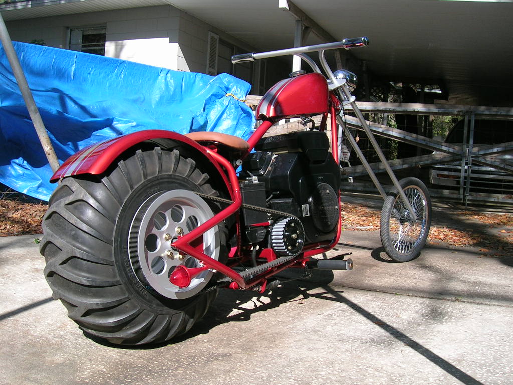
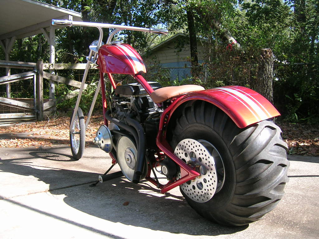
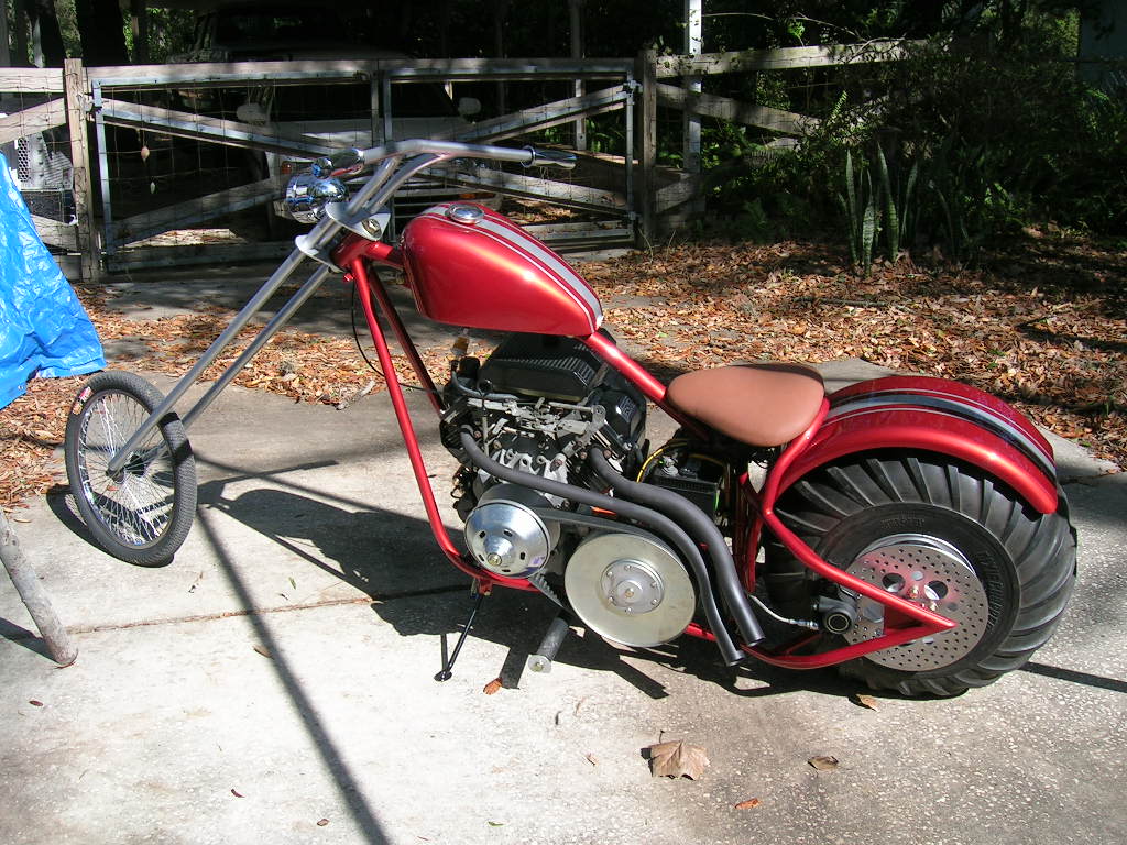
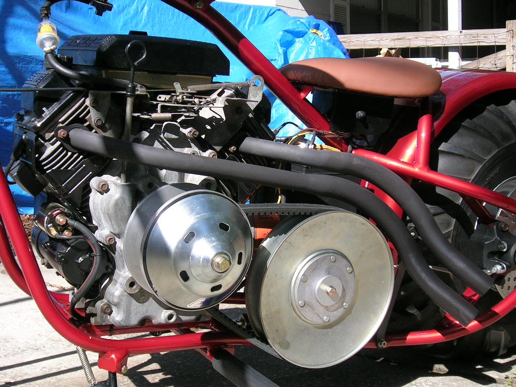
1.) A huge engine! No 5hp or even 15hp but a 25hp Kohler CH25S 725cc V-Twin.
Vanguards were the norm so I wanted something different, Kohler fit the bill
with hydraulic lifters, nickel silicone plated cylinder walls and electronic
ignition
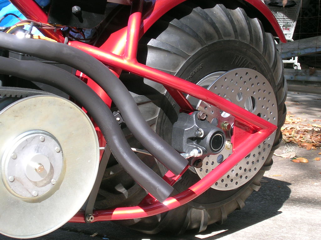
2.) Hydraulic disc brake with a remote reservoir for master cylinder
3.) Cog belt drive system. No chain to oil or make noise doing 60mph
4.) A dead rear axle. The wheel/hub will rotate over the axle on sealed bearings
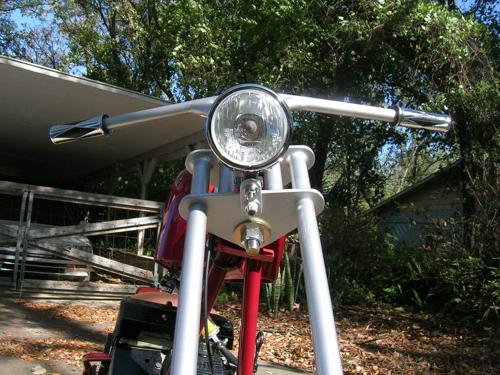
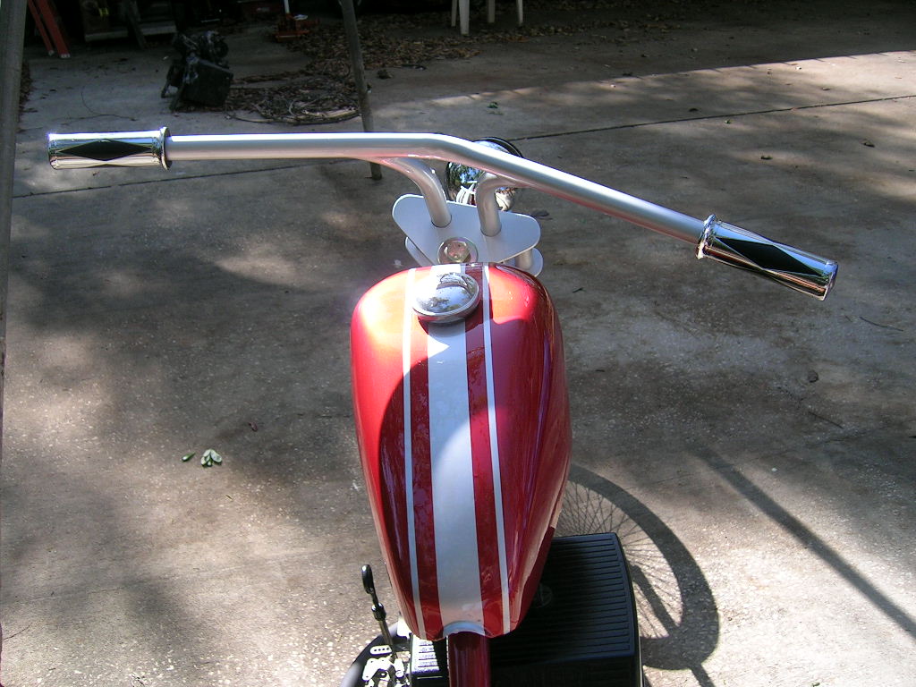
5.) Internal throttle handlebar system for no unsightly wires or cables like
real chopper builders use
6.) Headlight and brake light system
With such a large engine, right away several problems were presented:
1.) Transmission: a centrifugal clutch was out of the question. Comet's 20 and
30 series TAV's were also too small. We had some success from the Comet 40
series torque converter on the go kart application, but Comet only recommends
the 40 series for up to 16hp and now I see why. With 25hp and a heavy go kart,
the roller weights are not heavy enough to engage the belt to keep from toasting
it. So the clutch "slips" for a longer than normal period. I won't go into
detail about the go kart's specs, but the 40 series did work well for what it
was, but a bigger clutch could have made things work even better. So with that
now known, I was now in snowmobile territory looking for the 94C driver.
Snowmobile clutches are not purchased in "kits" rather everything is separate.
Once I got the driver and driven clutch pulleys, a belt length had to be
determined. This proved way harder than just flipping through a parts catalog.
Long story short, Don Jackson of
Comet Industries
personally sold me a "proper" belt according to the specs I gave him. Rarely
does a manufacture sell and ship a product directly. Bear in mind this belt
dilemma was very stressful as it was one of the last items purchased insuring
the engine to rear axle distance was as short as possible. The belt finally
showed up after the frame was just tack welded and pulleys were in place.
2.) Battery: the engine actually has electronic ignition, so it will not fire
without a minimum of 10 volts to the circuitry. This means a battery will have
to be on-board at all times. This really was not a problem as no engine above
18hp can't be easily started by rope/recoil. But an almost fully charged battery
is a must.
3.) Foot peg position: with the engine being so wide with the clutch pulley and
exhaust mounted, it created a minor problem for rider position. This was later
remedied by moving the foot pegs rearward.
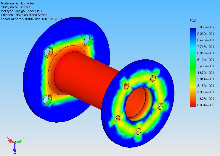
Before any construction began, part of my project was to simulate the stress
being developed on several items: the pulley drive hub, the axle shaft and the
front fork. I used two methods for determining the stress in each component; (1)
analytical (mathematical/textbook) and (2) FEA (finite elemental
analysis/computer software simulation). Both methods gave very similar results
(a very good outcome when practicing engineering!). A safety factor is a number
assigned to a part which tells how many more times stronger it is until failure
will result. So 2 means it is twice as strong, 3=3 times as strong, etc. As it
turns out, the pulley hub has a safety factor of 8.7, so it is fairly strong
considering the weight it will carry and the torque being applied to it from the
engine/transmission.
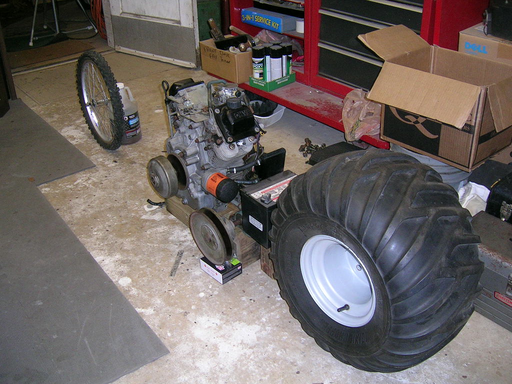
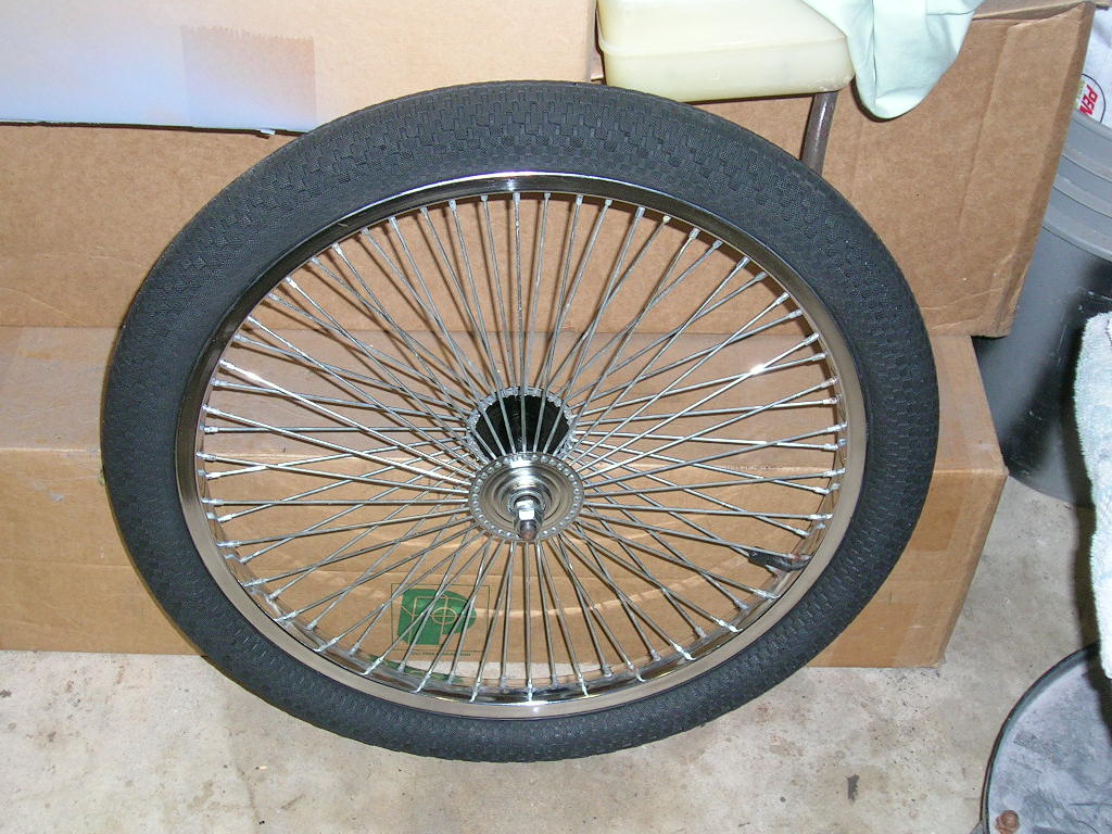
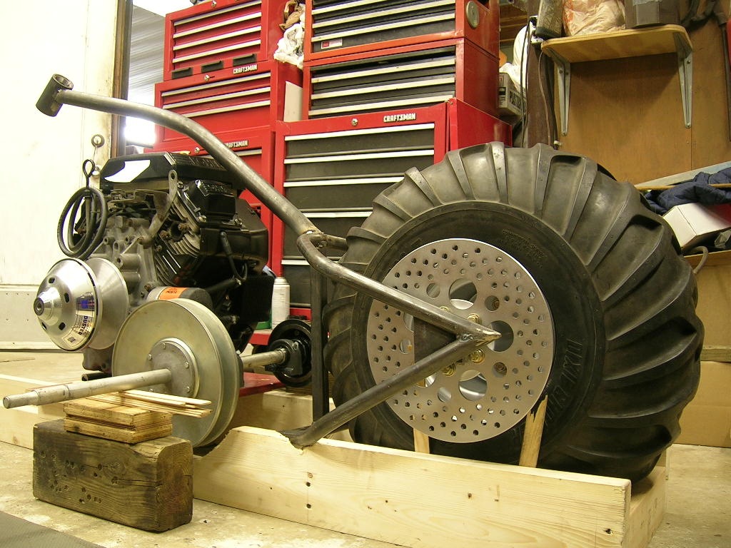
At the start of February, this is what I had: an engine, front and rear
tires/rims and a Comet 40 series torque converter along with a dead battery.
Within a week I upgraded to a better front rim with many more spokes to carry
the substantial weight of the Kohler V-Twin:
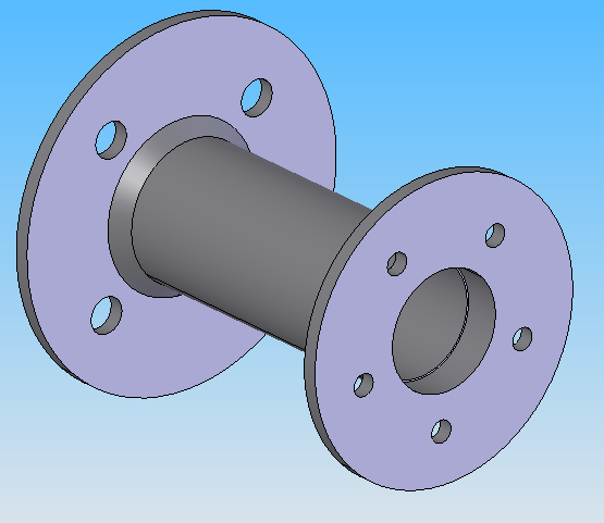
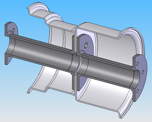
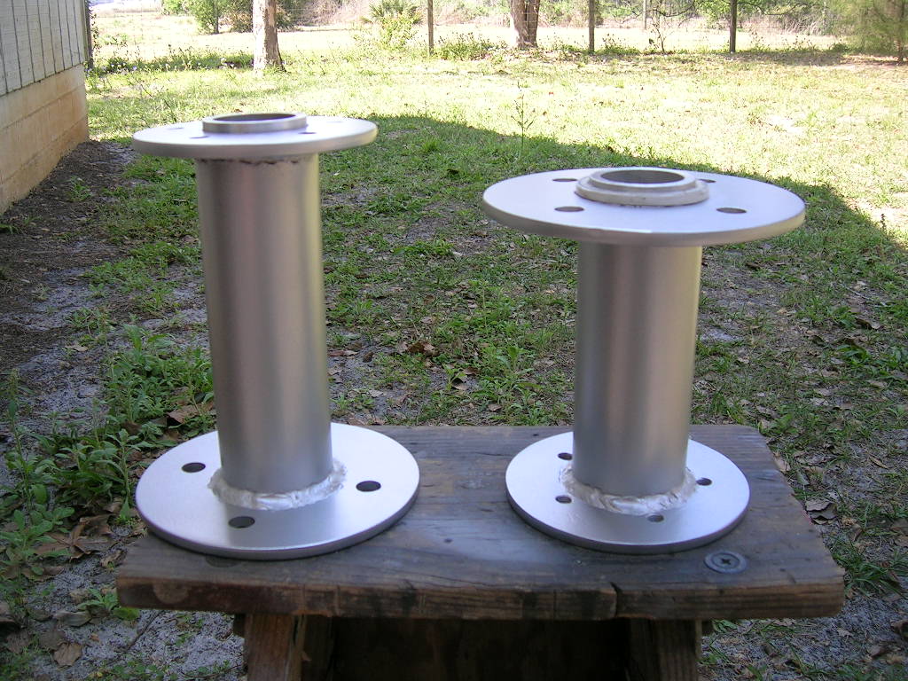
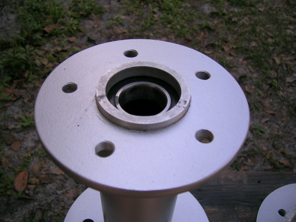
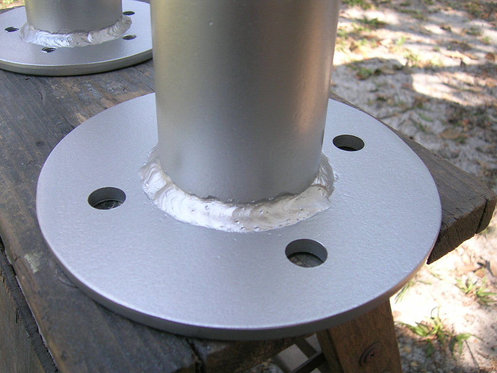
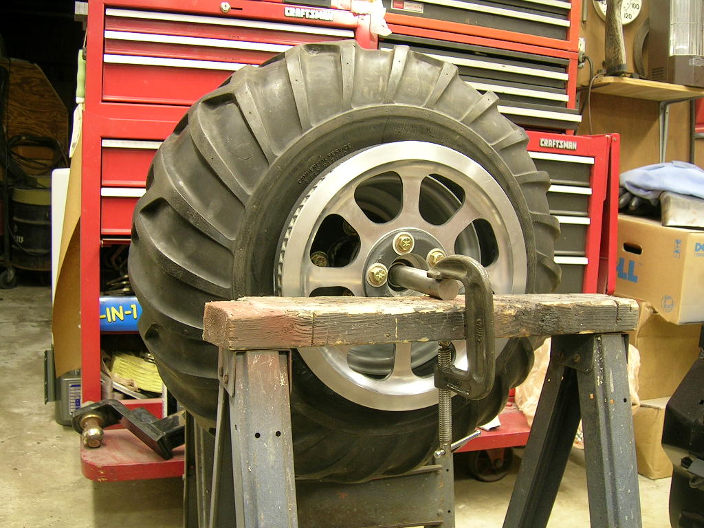
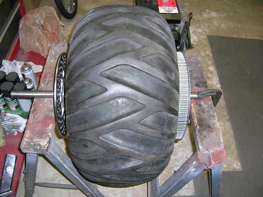
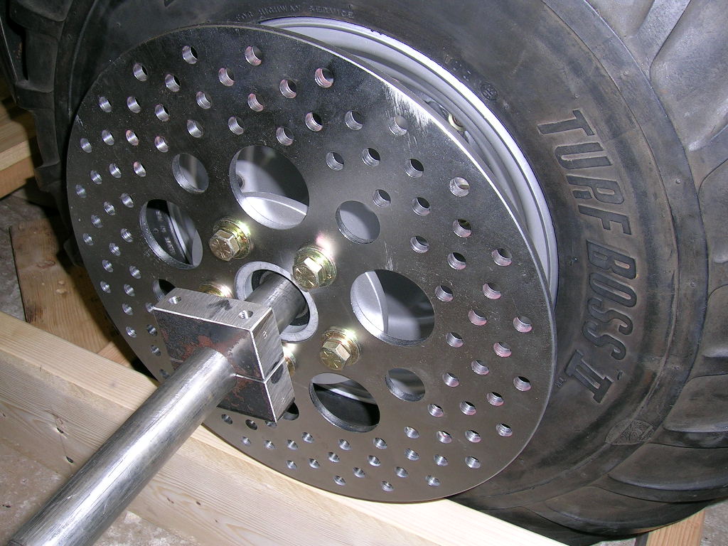
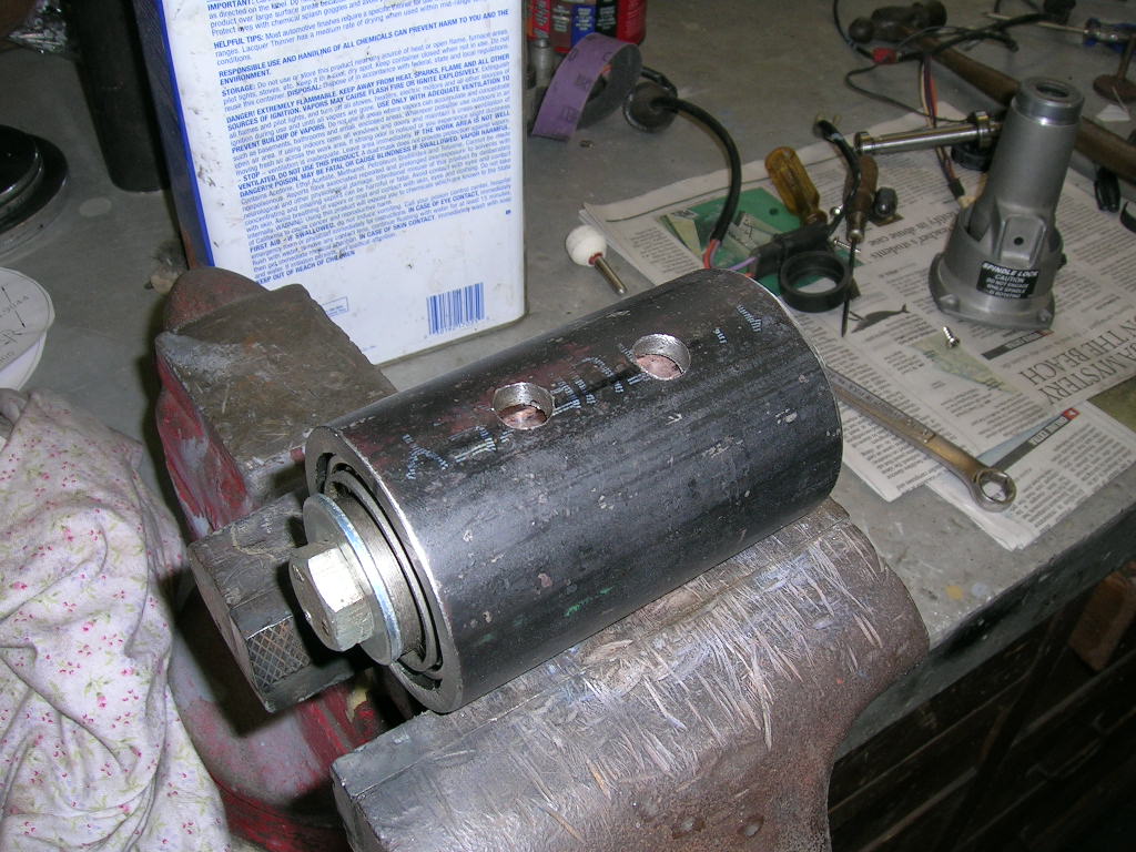
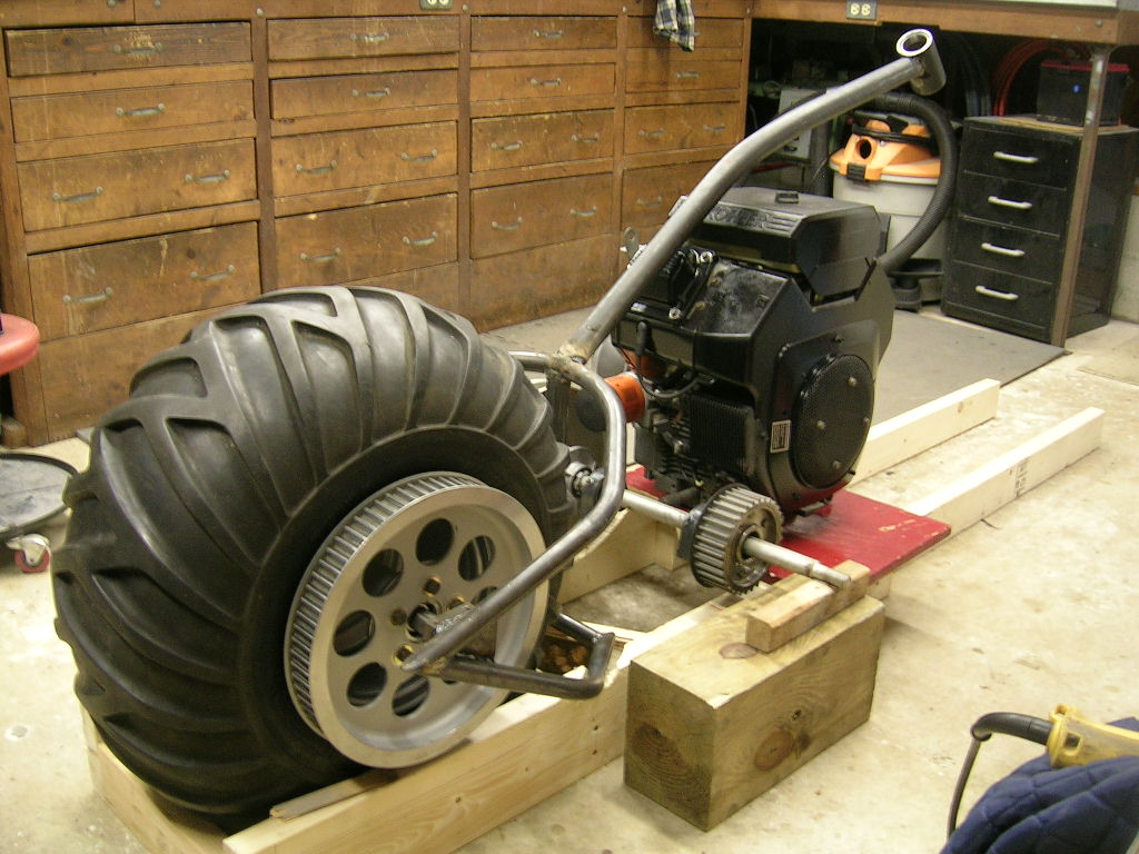
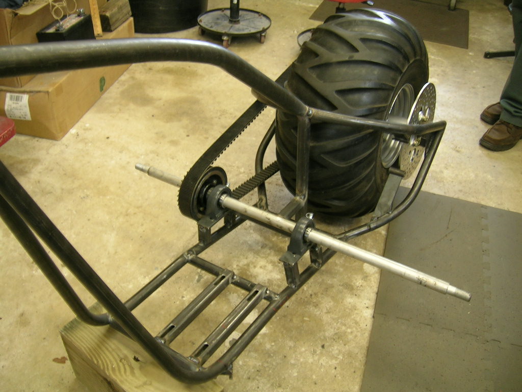
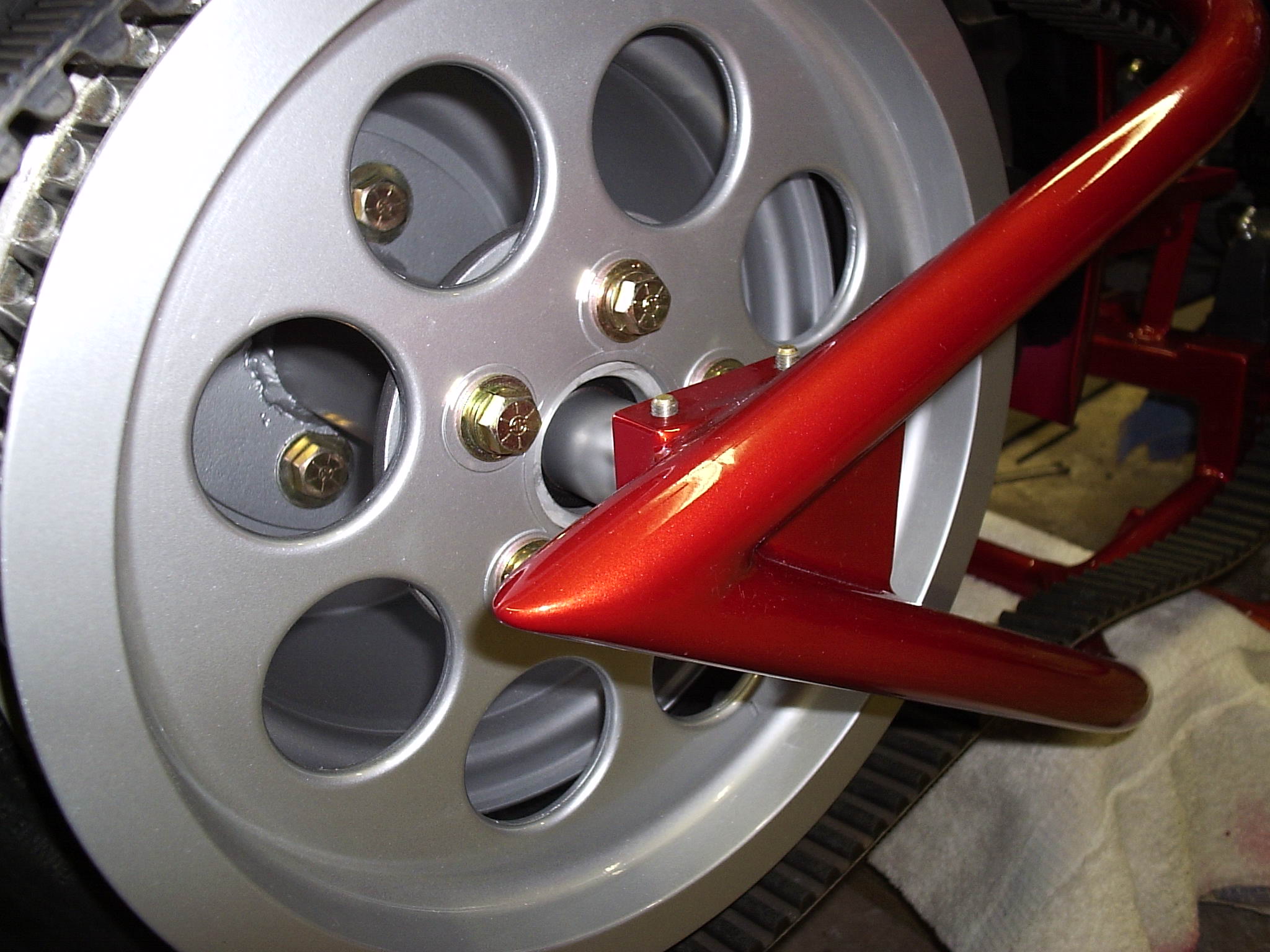
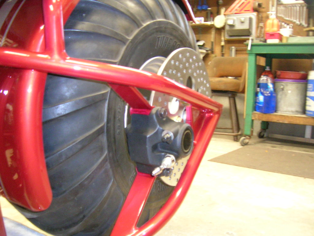
Starting with the rear, I needed to make my own hubs
to bolt to the rim since nothing like them exists anywhere else (adapting a
lawnmower rim to Harley Davidson belt sprockets and brake rotors). It was just
easier to make my own parts rather than modify go kart parts. There will be two
hubs, one for the belt pulley and the other for the brake rotor. Below is a
picture of what needs to be created:
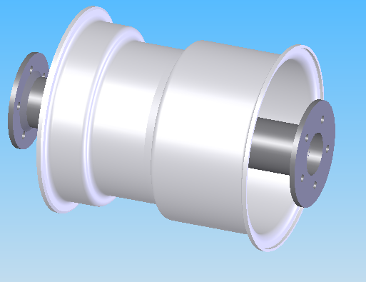
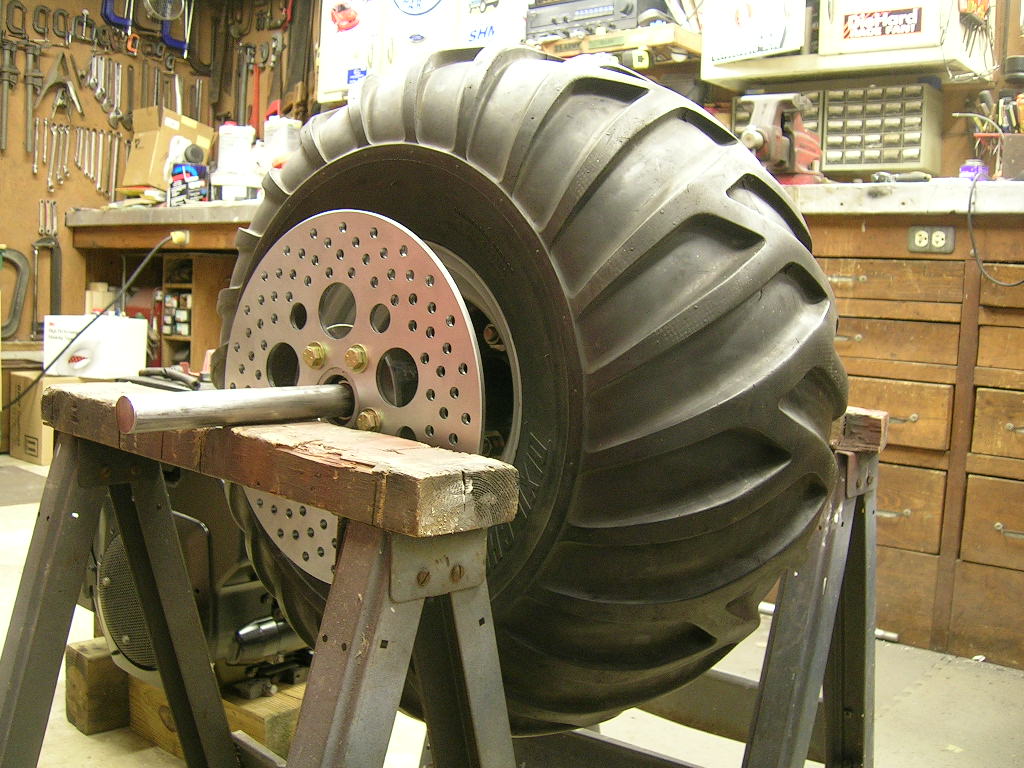
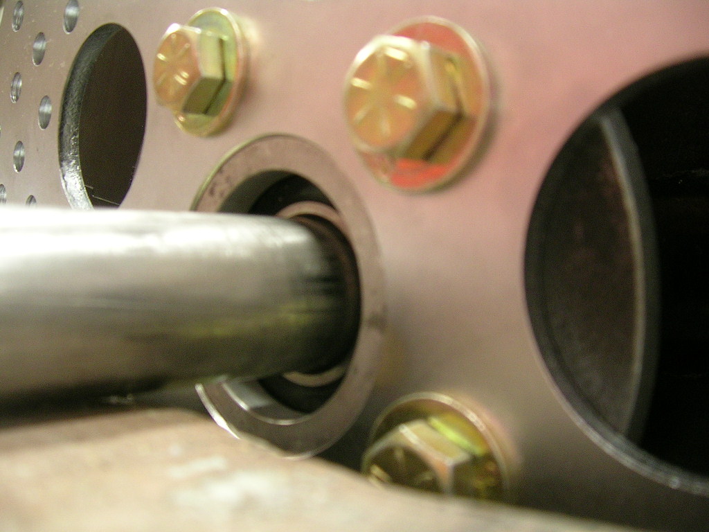
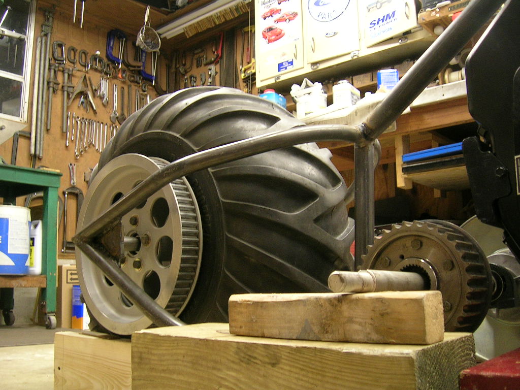
Now with the addition of both hubs and the rim in
between, below shows the rear wheel assembly in a cross section view:
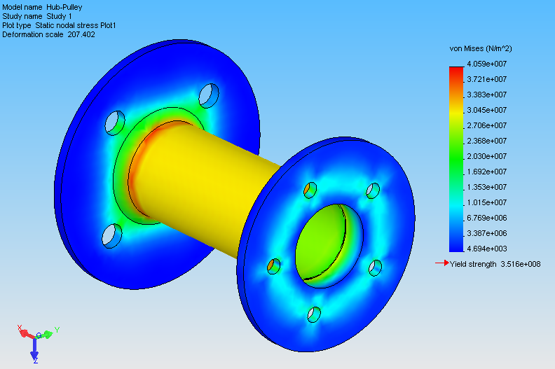
Here is a graphical representation of the stress
developed within the pulley hub:
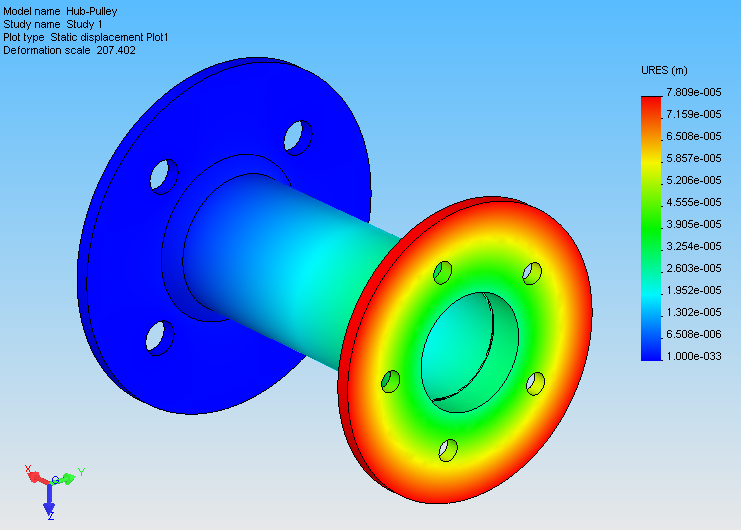
Here is a graphical representation of the
displacement developed on the outer edge of the pulley hub:
Here is a graphical representation of the factor of
safety developed within the rear hub:
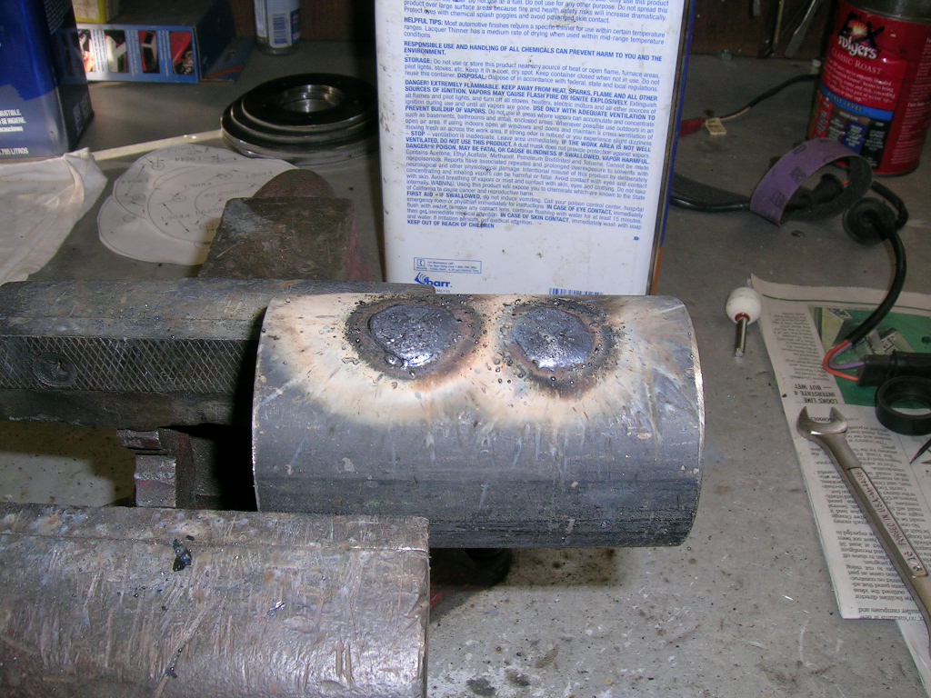
The hubs were made of ASTM 53 1020 steel tubing.
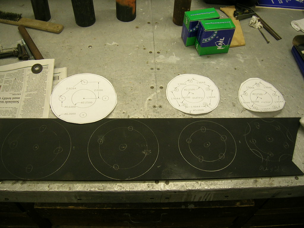
Then the wheel and rotor/pulley flanges were made from ¼” flat stock steel.
AutoCAD was used to make a pattern which was traced onto the steel via paper to
be cut out:
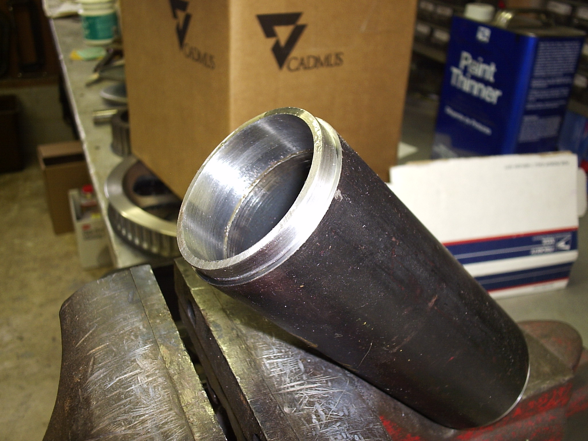
We took the tubing and plates to a machine shop so
the plates would press on over the tubes resulting in a near perfect trueness
when spun:
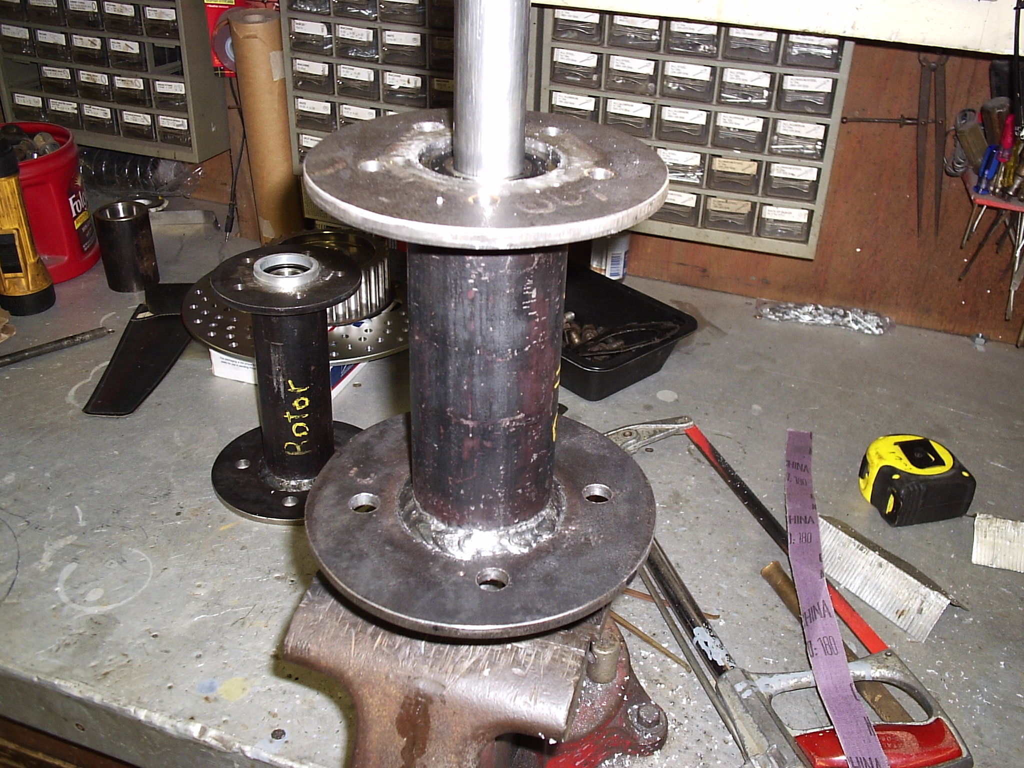
The plates were then welded on the backside of the
tubes. Some warping did occur, but luckily the warping was equal around the
entire flange so it does not wobble. A little heat of the torch and a few whacks
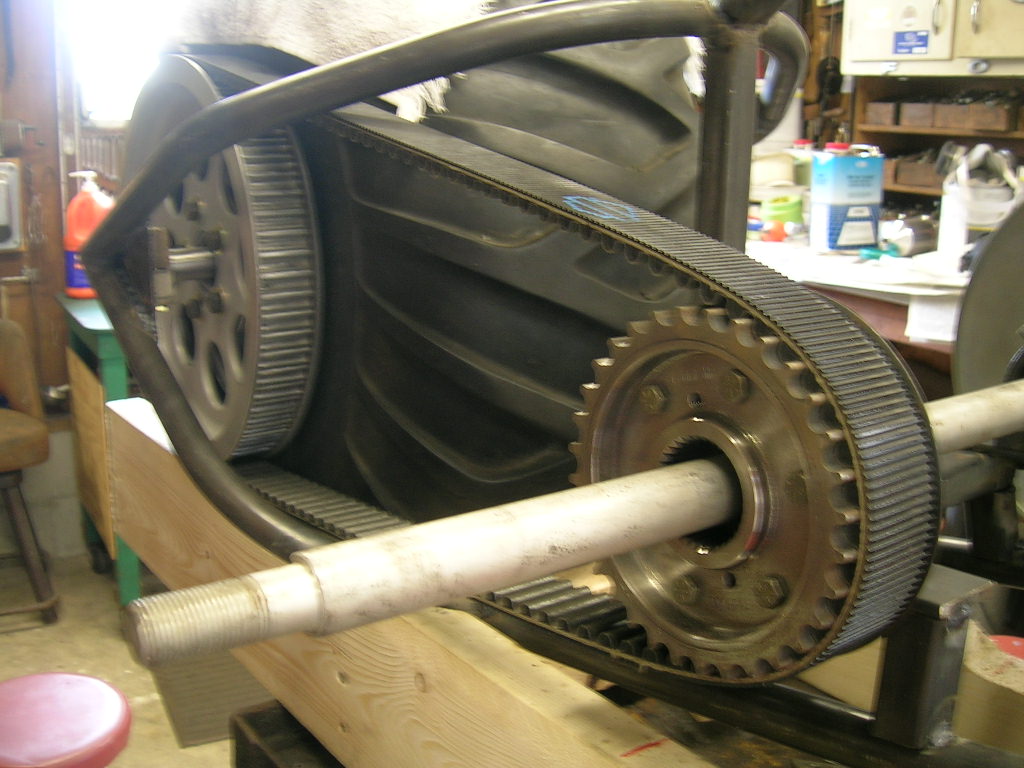
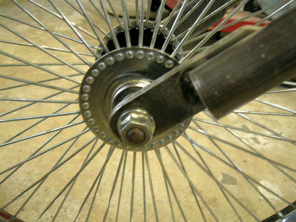
with a hammer and it was true to .005” run out:
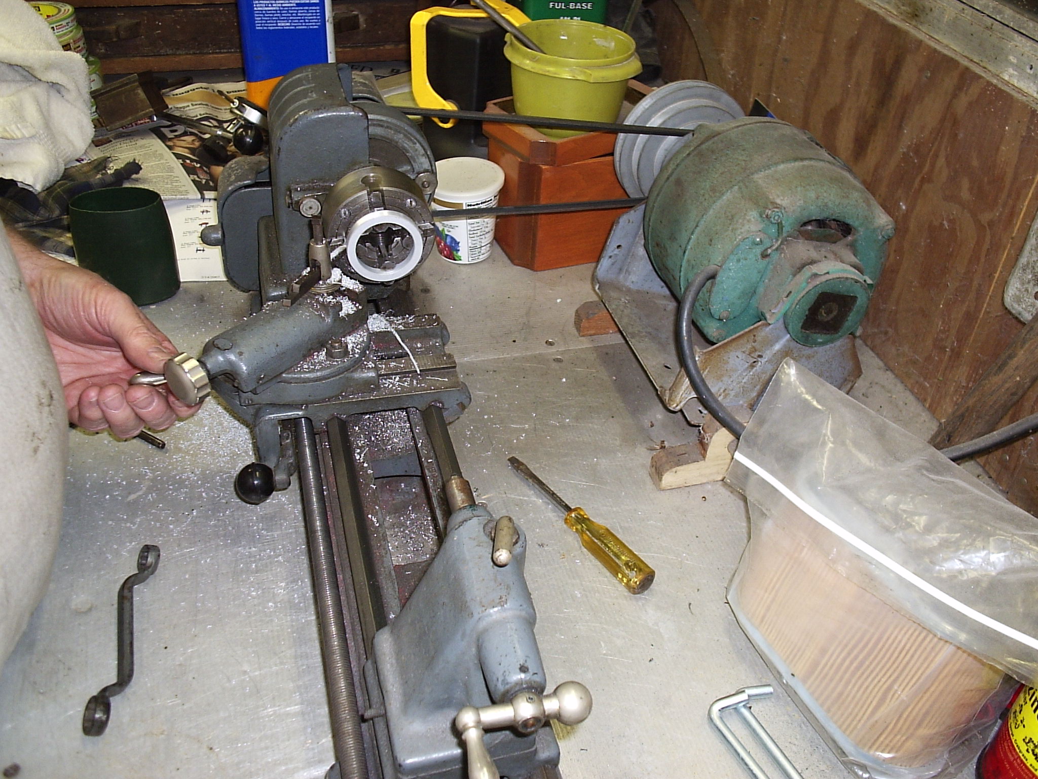
Next, we needed a way to center the pulley and rotor
on the hub flange rather than relying on the bolts to do this. So we used our
Atlas model 109 lathe to turn some aluminum spacers that were ironically found
from a 1980’s vintage computer hard drive (when the platters were over 5”
diameter!) They were just the item:
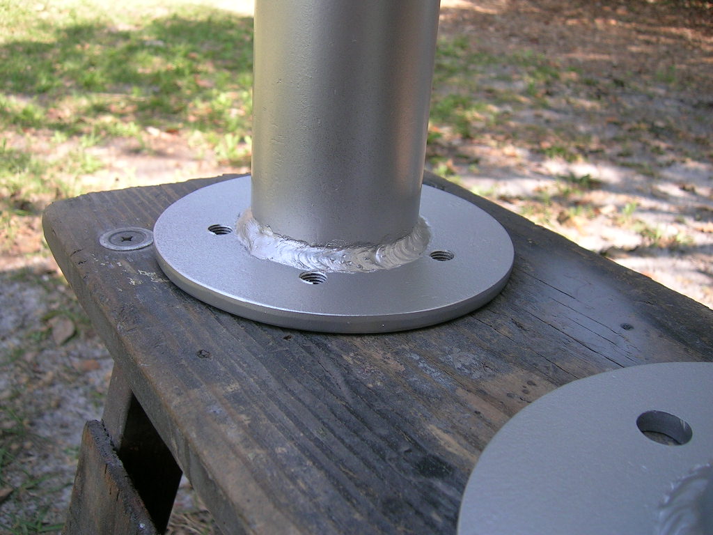
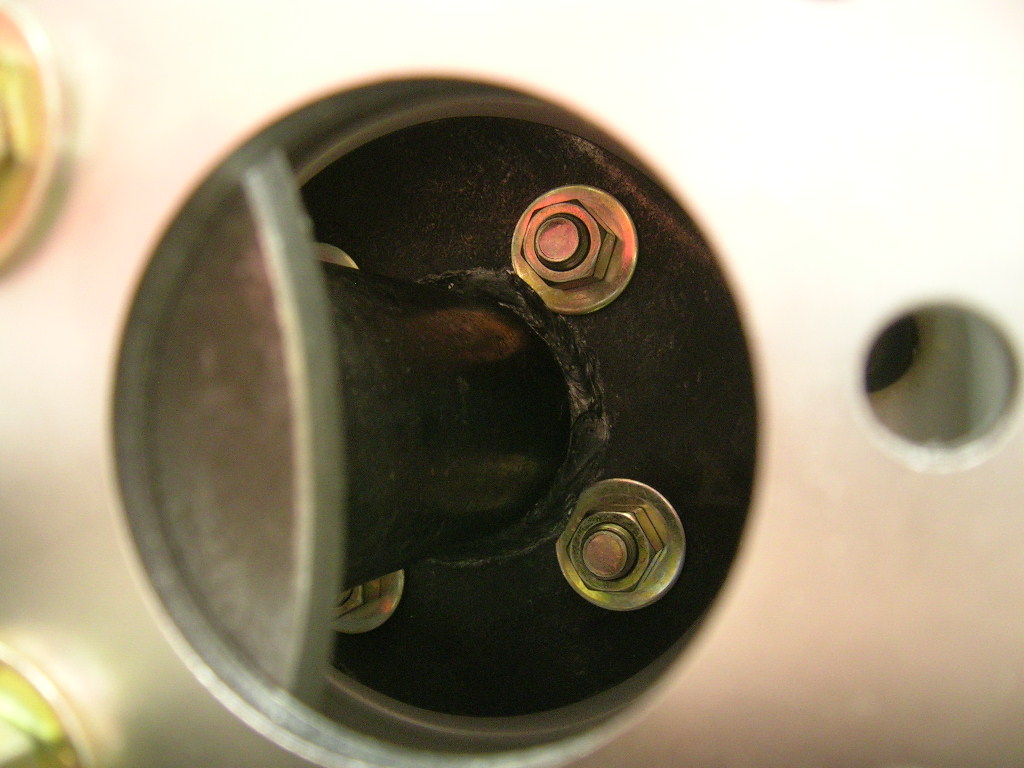
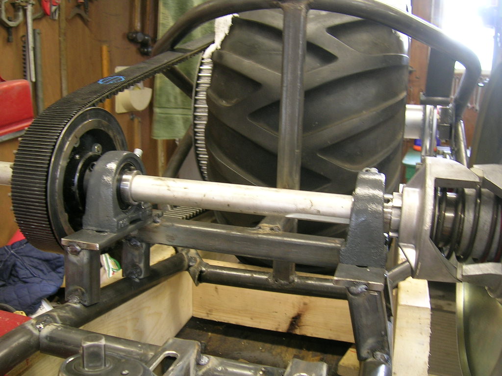
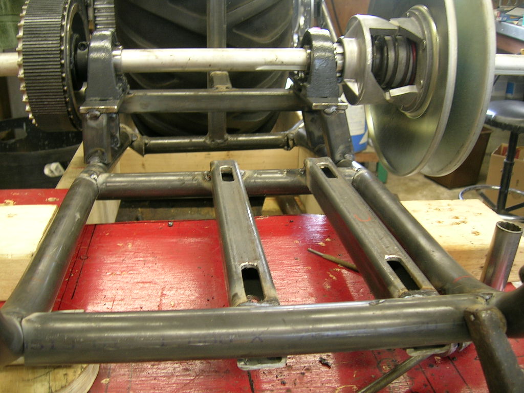
A test fit of the entire rear assembly spinning on
the axle shaft:
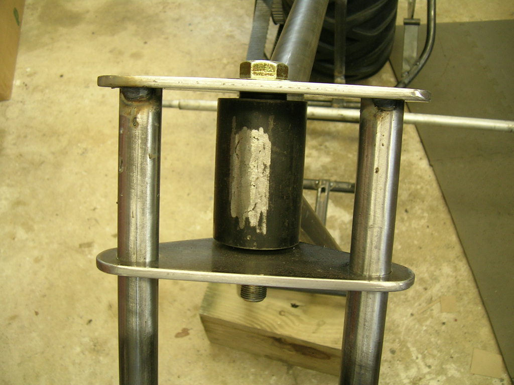
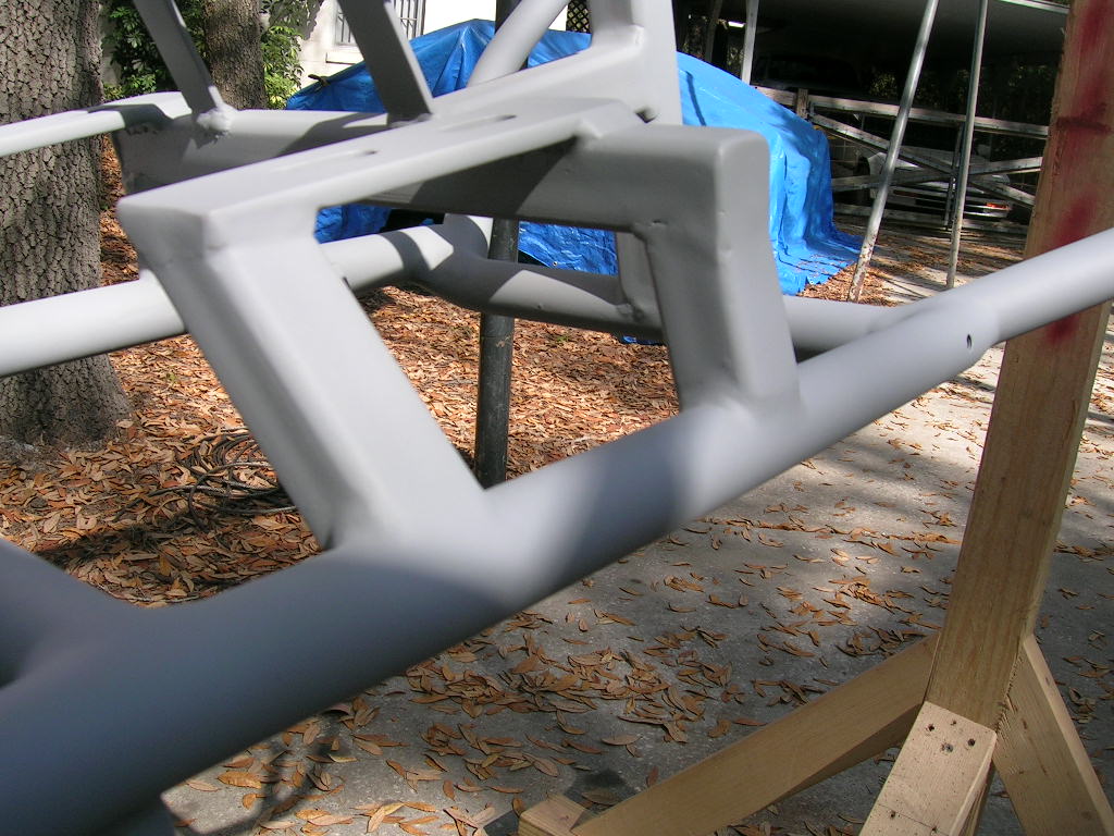
Now the axle mounting blocks are created. One half
will be welded to the frame, while the other half will clamp the axle by means
of two fine thread bolts:
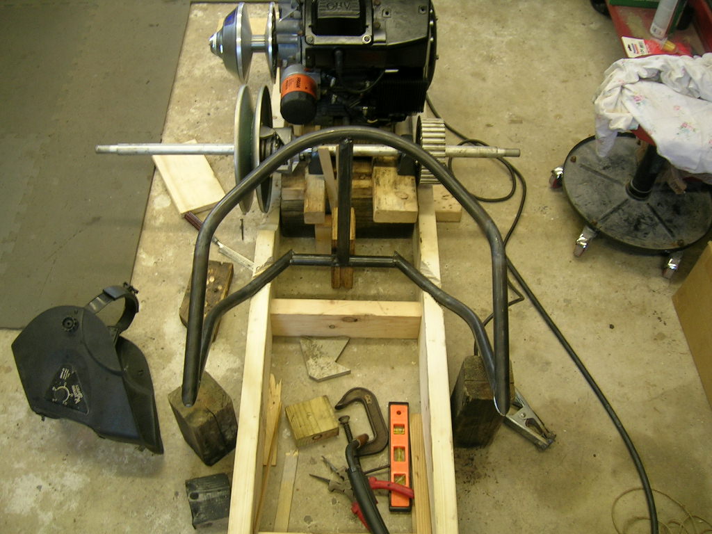
After that, it was finally time to begin building
the frame. A jig was needed to hold everything stationary and upright, so one
was built with 2x4’s and 2x6’s. Since we are not in the bike building business,
the primitive method of wood was used rather than steel. We started with the
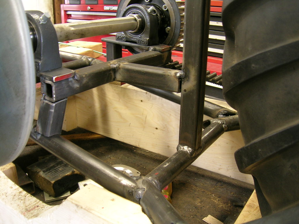
rear “horseshoes” around the rear tire:
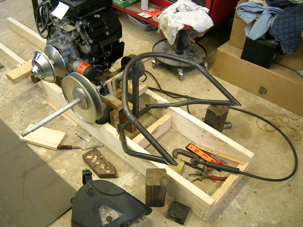
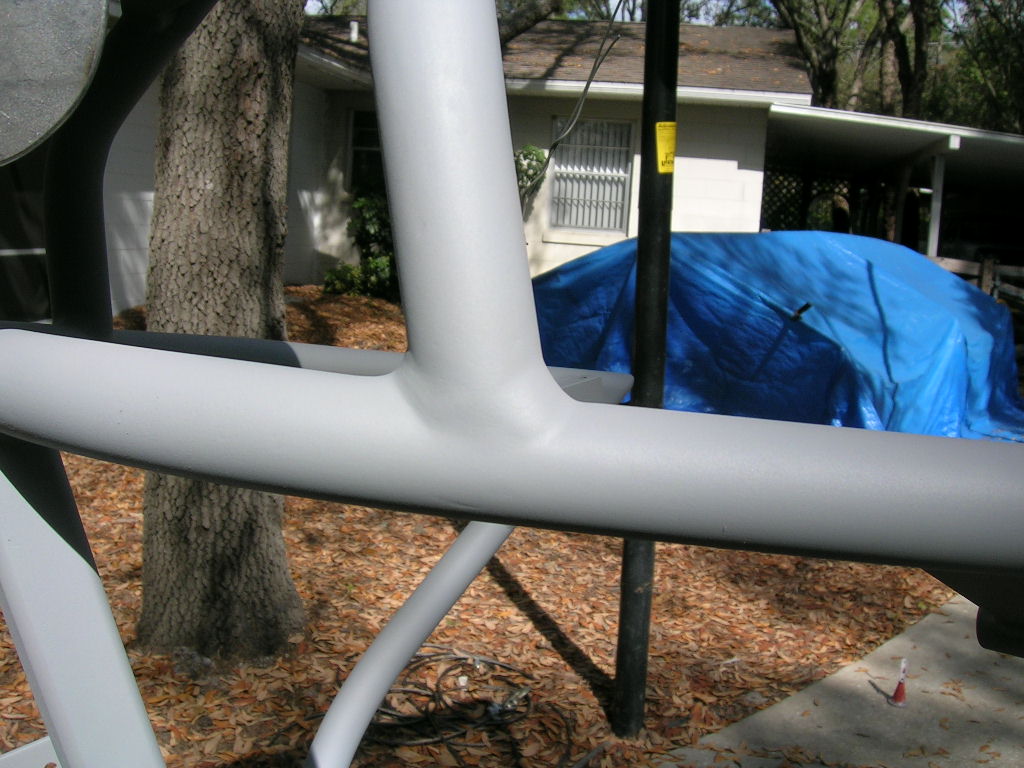
Once the rear section was finished, work was turned
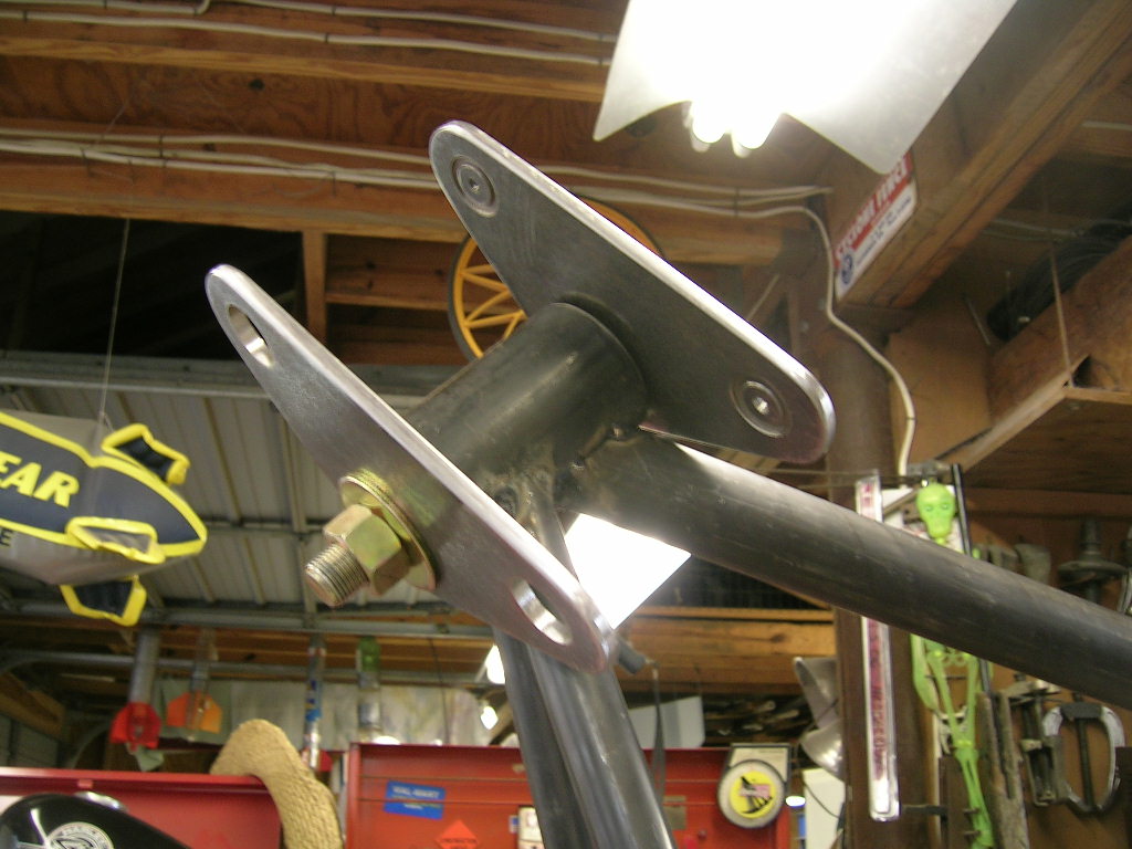
upwards of the backbone and to the steering neck. I chose to use two tapered
roller bearings rather than bushings or even steel on steel friction. This
ensured greater weight capacity and smoother steering without any play:
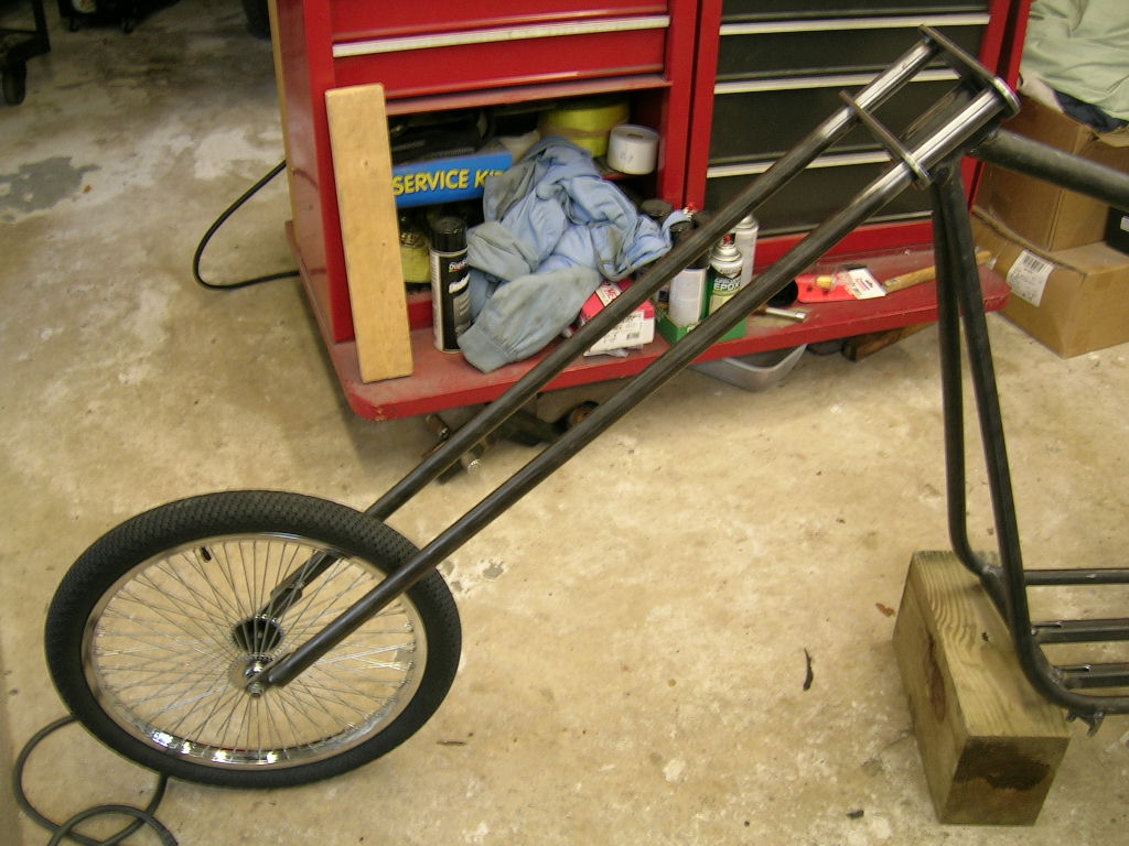
The backbone was then bent to an eye-appealing curve
and test fitted:
Sadly enough, no photos were taken of the twin down
tubes going into place. We were on a role that day as pieces were fitting
together like a adult fitting a pre-school puzzle. The hardest part was getting
both down tubes to match exactly with the pipe bender. After they were tacked
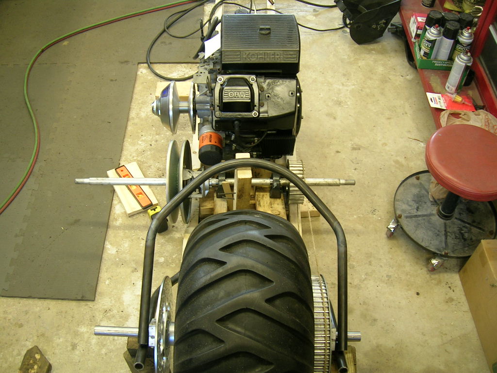
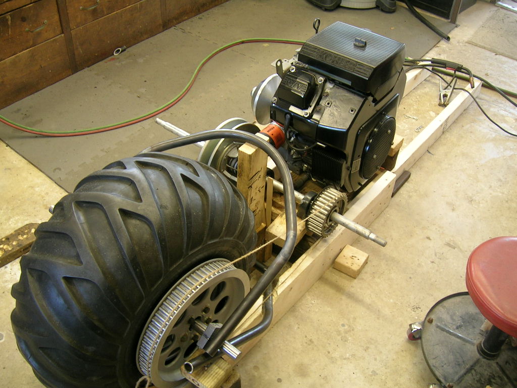
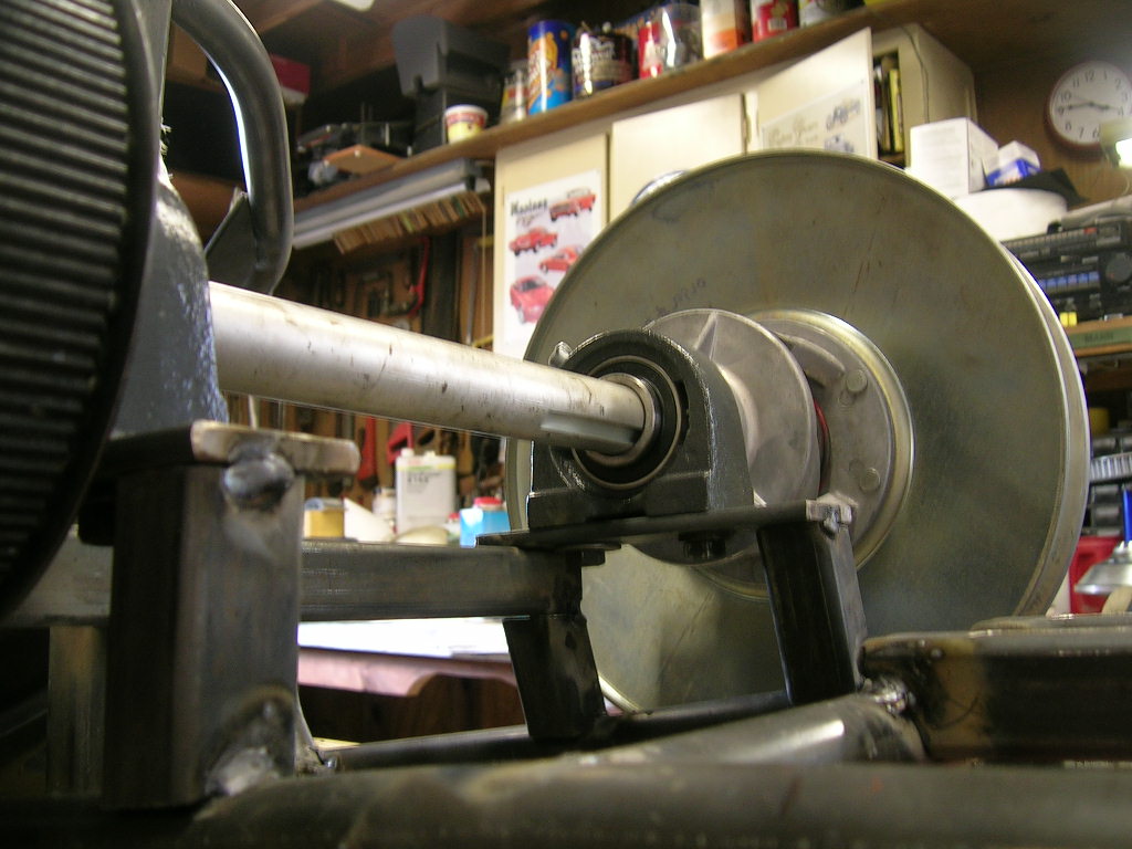
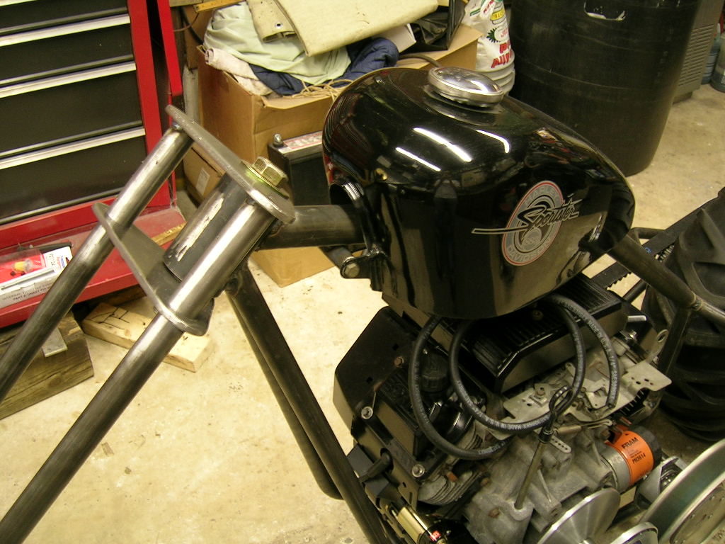
in, attention was turned to the jackshaft and engine mounting tubes:
After the down tubes were completed along with the
engine and jackshaft mounts, the triple clamps were constructed out of more ¼”
flat stock steel. A slight recess was drilled for the ends of the fork tubes to
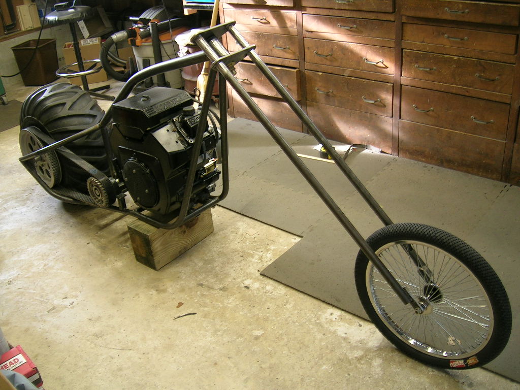
slide into providing centering and strength reinforcement. The bike was now
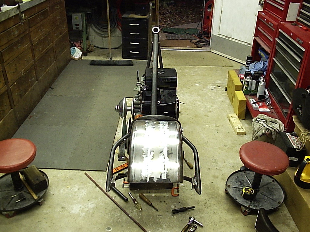
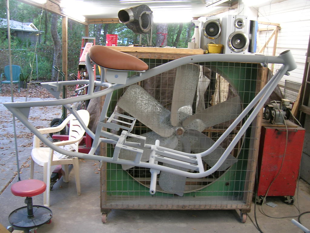
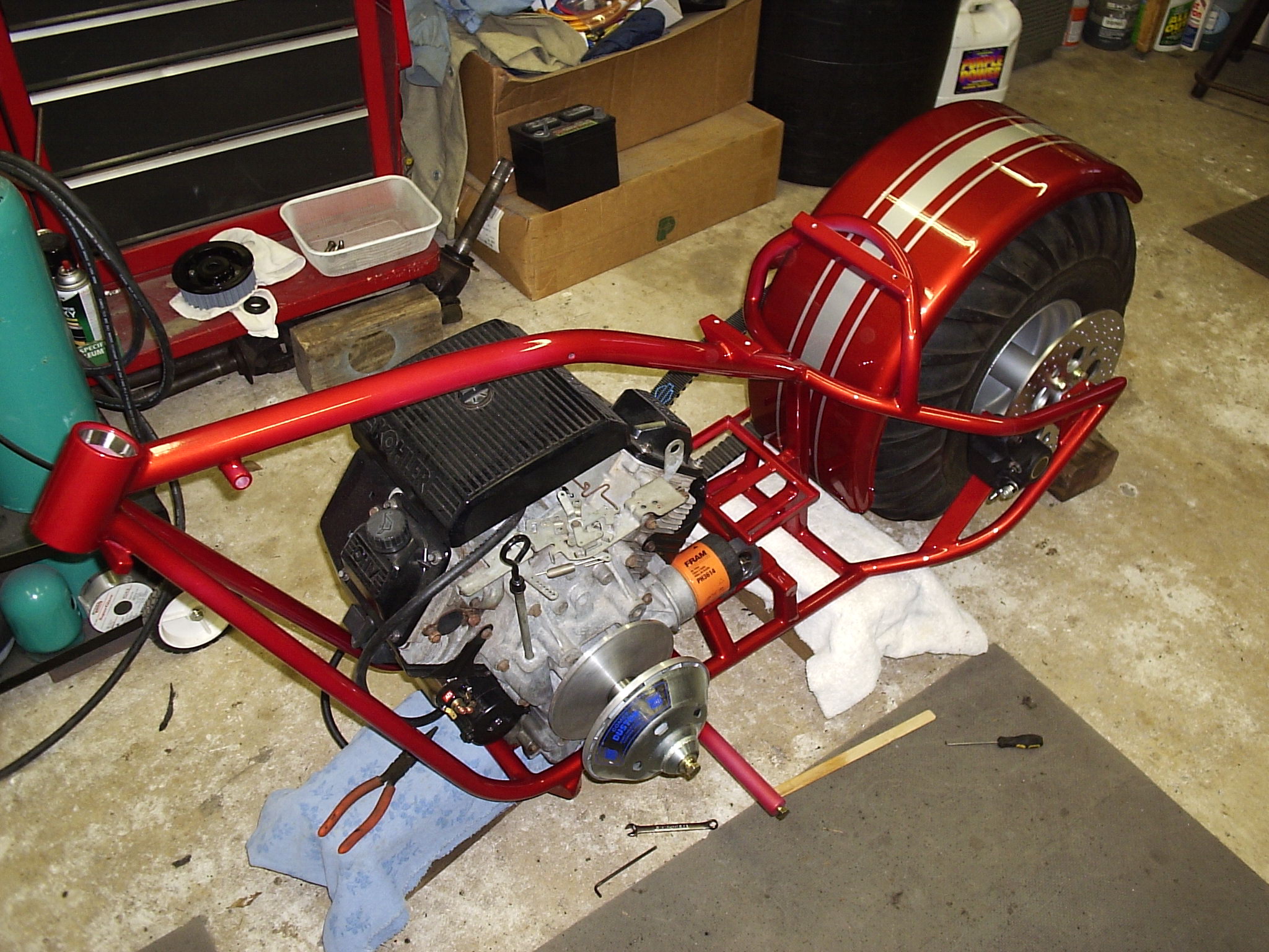
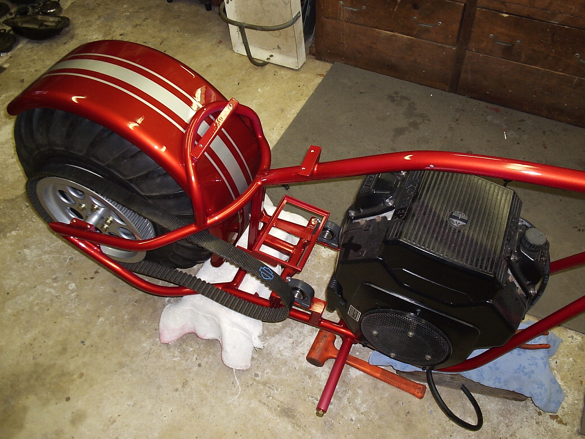
finally on its wheels:
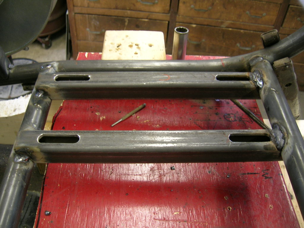
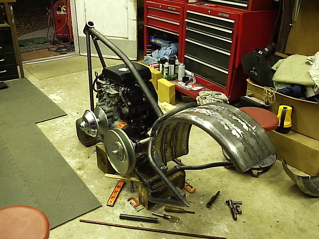
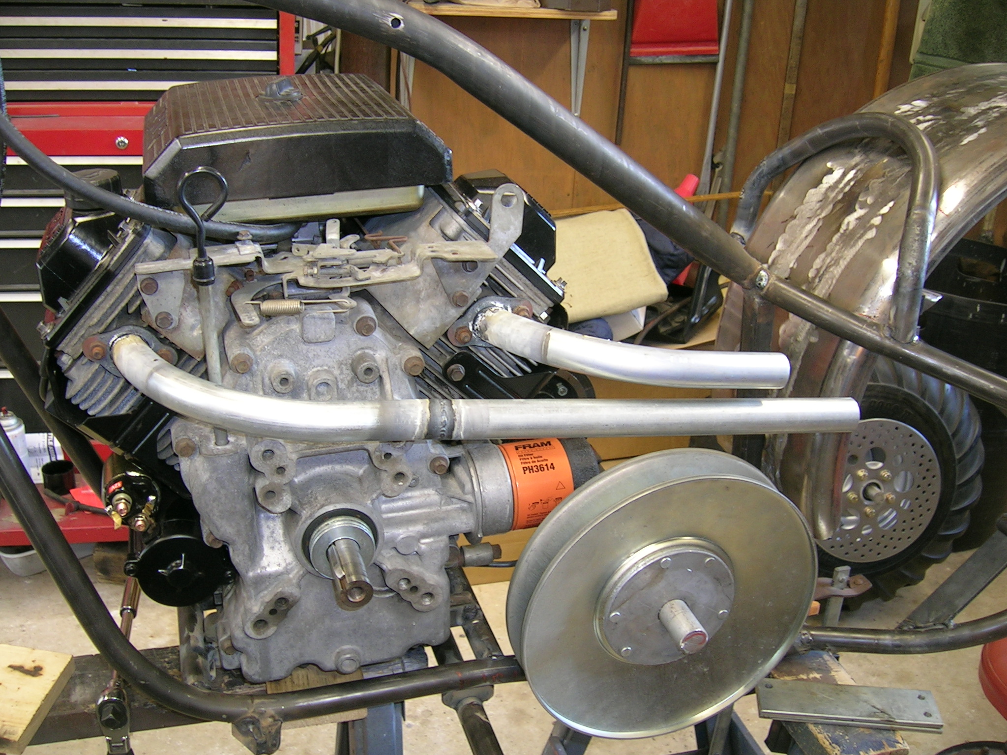
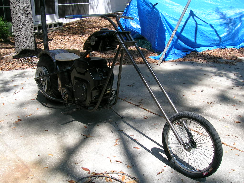
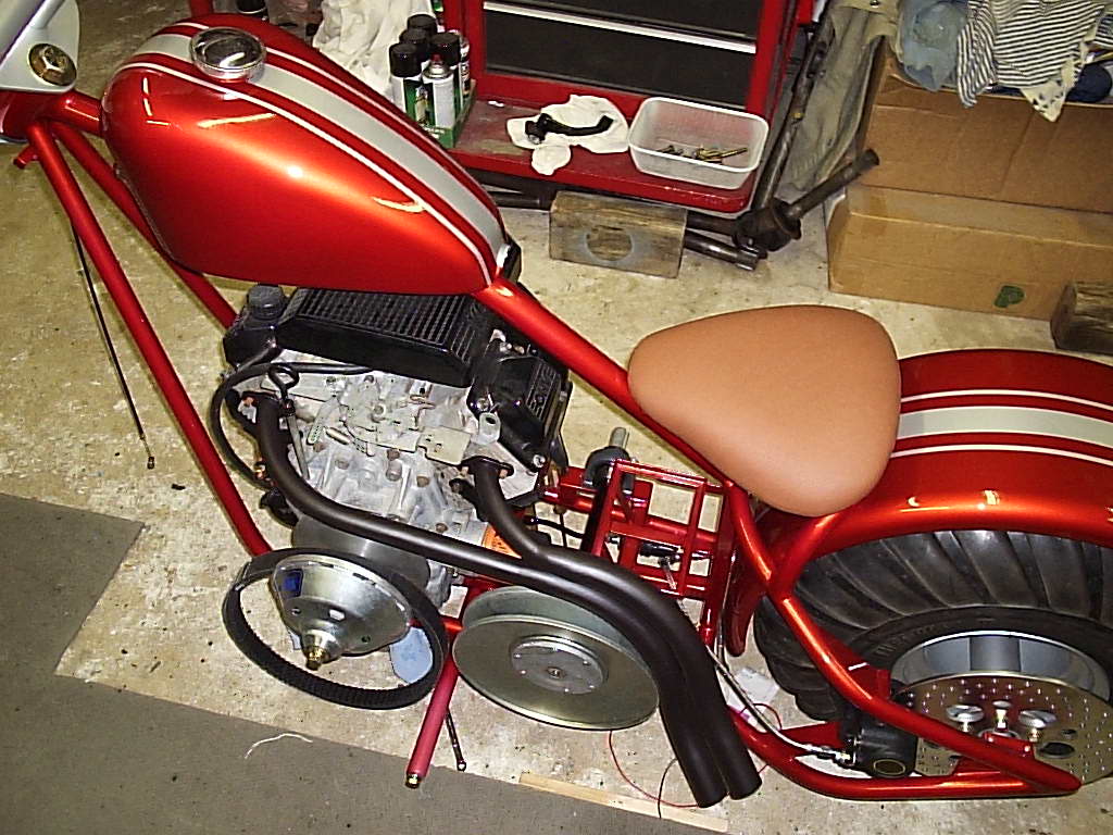
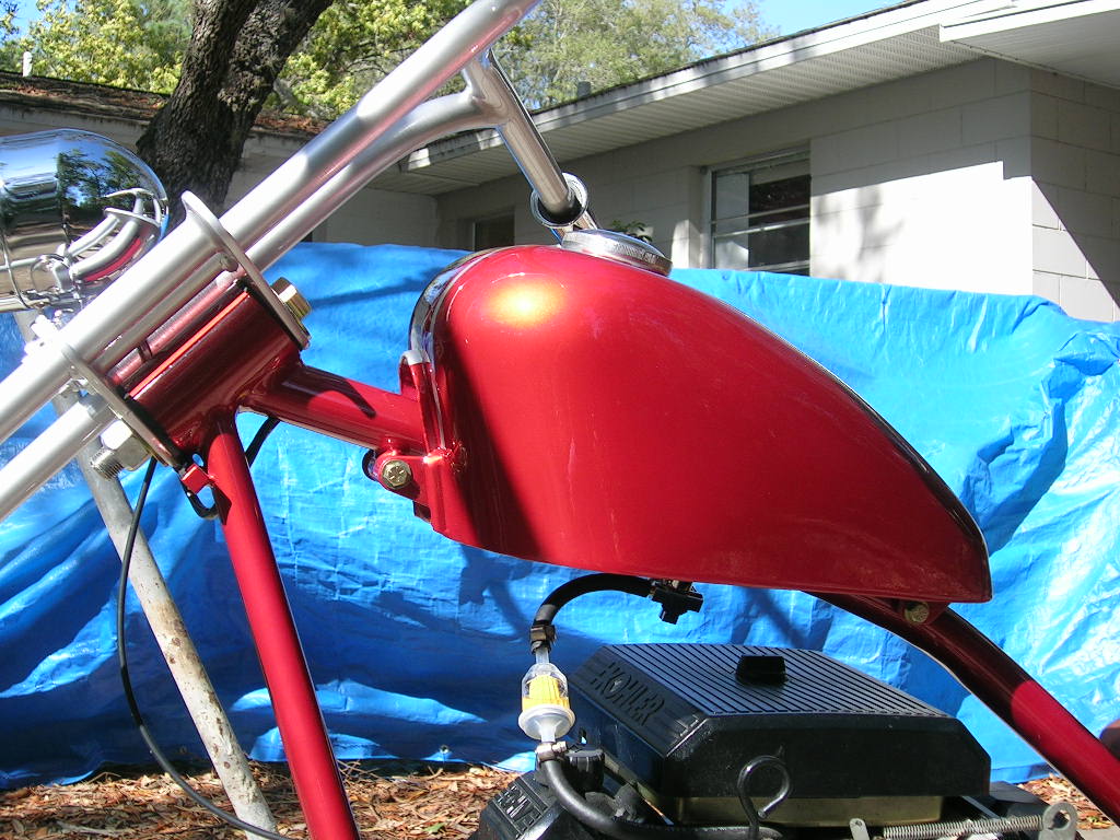
Next the engine and other components were set in so
completion of a few more items could be built such as the gas tank mounts and
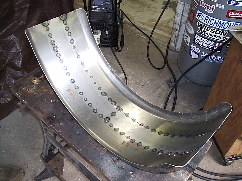
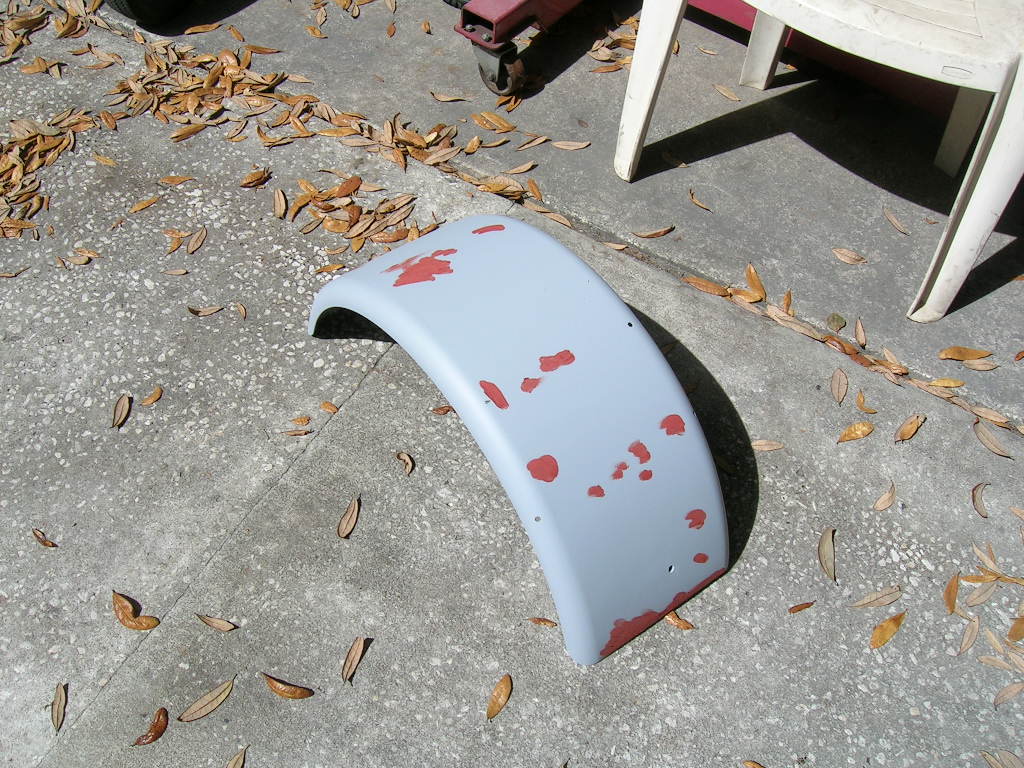
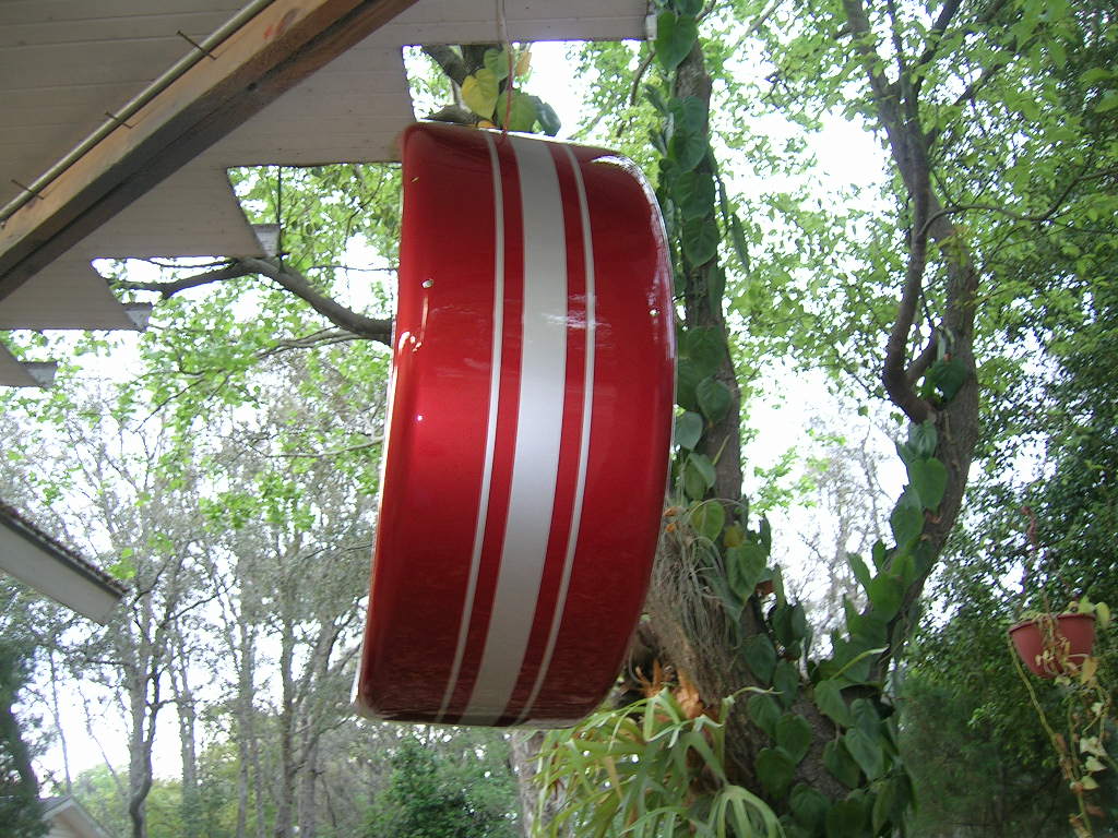
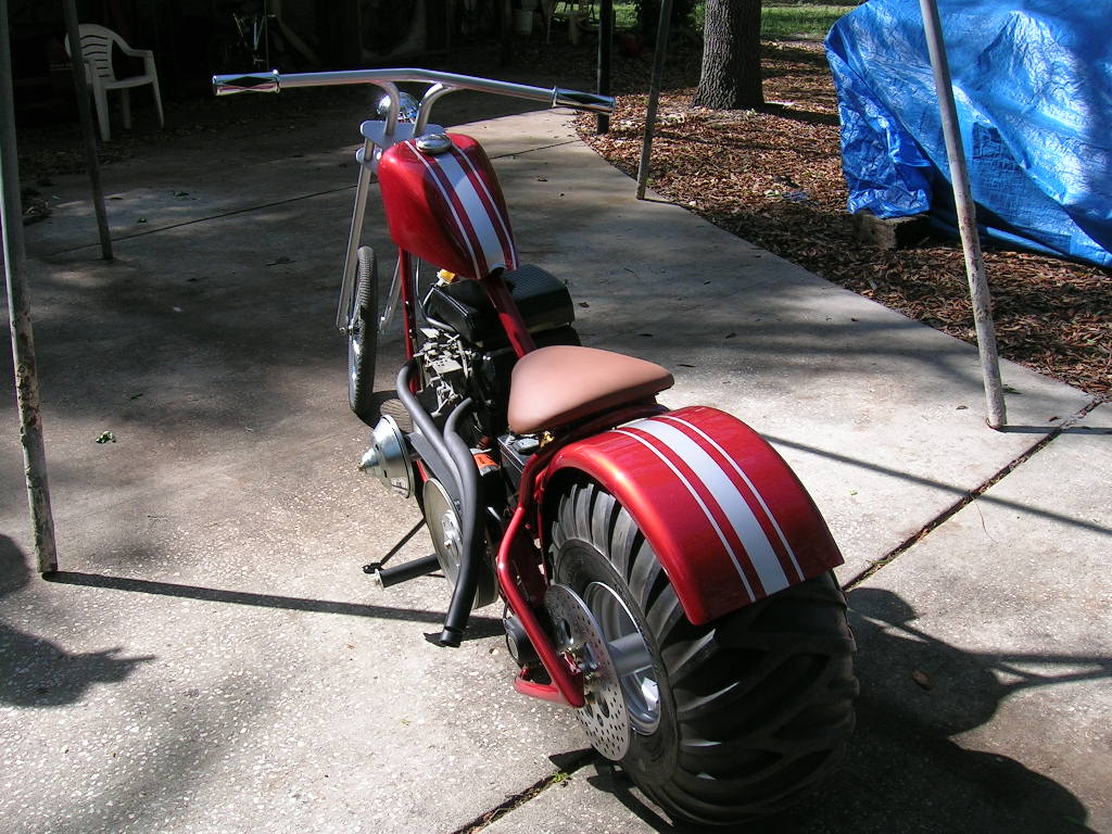
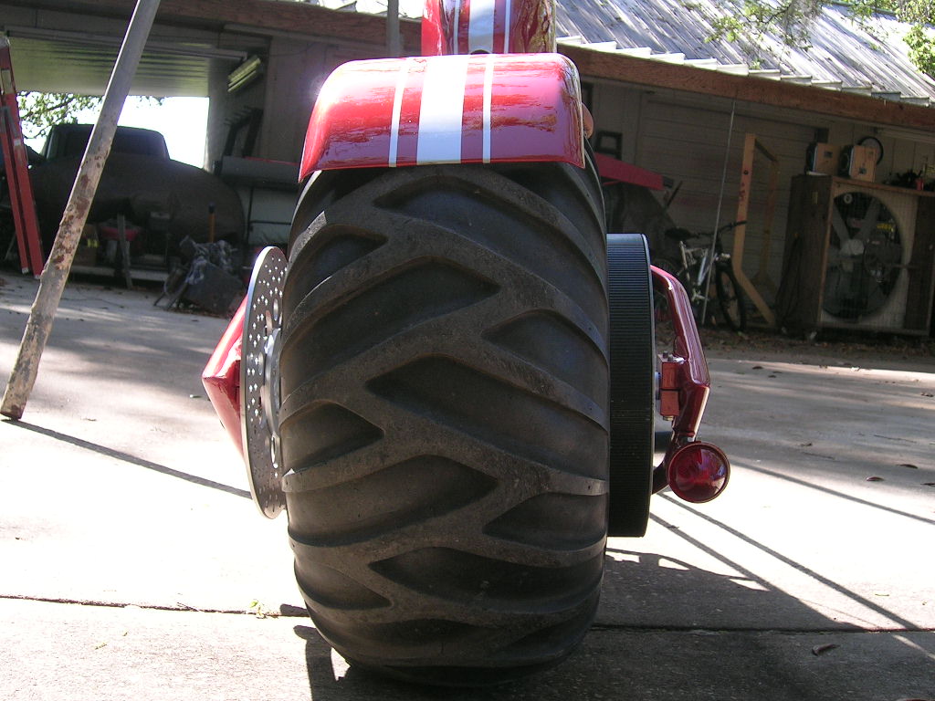
rear fender. The rear fender needed to be widened 3”. In these pics it is only
shown tacked:
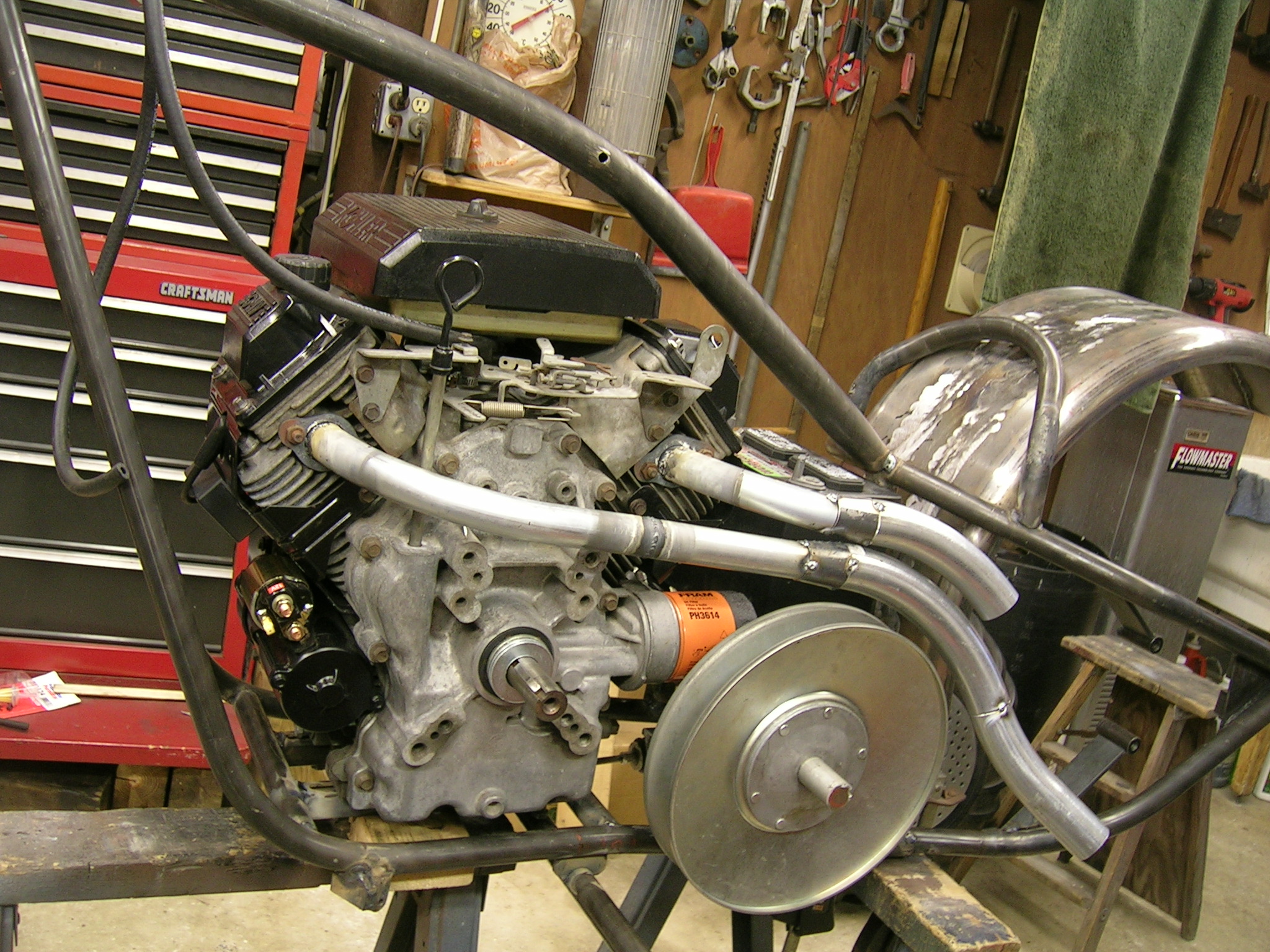
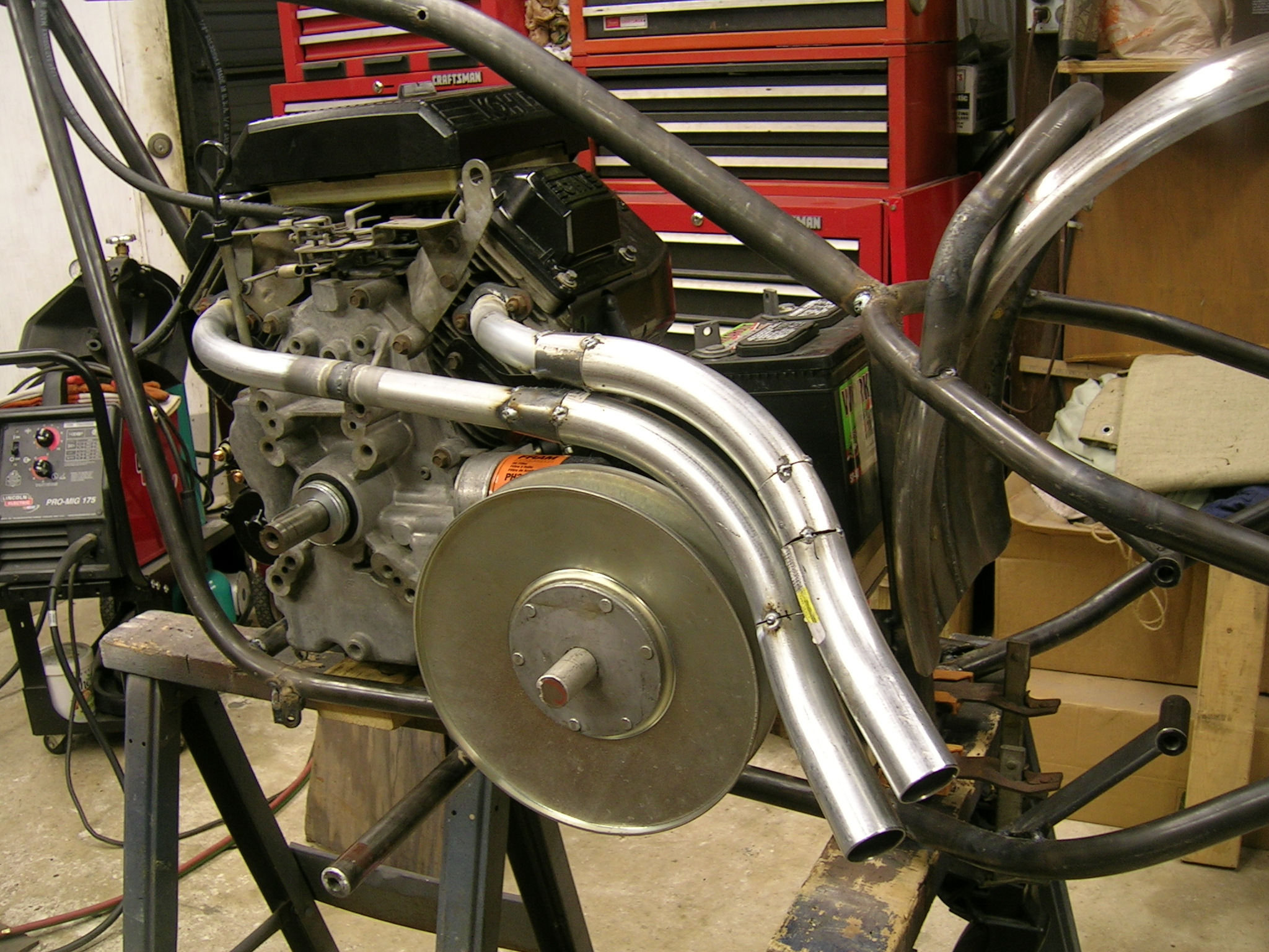
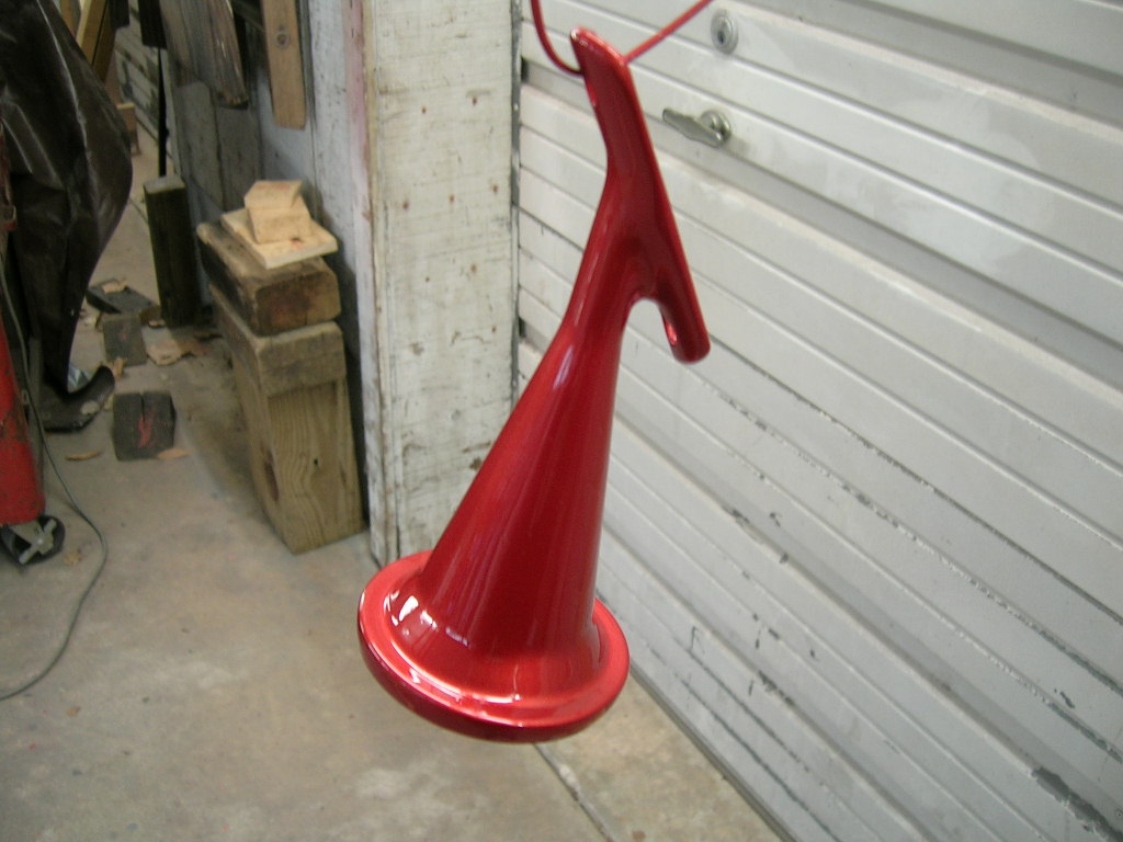
The exhaust was one of the last major items to
construct. Here we made our own head flanges and used EMT from Home Depot to
sculpt the pipes. It enlarges from 1” to 1.5” via a special cone we made from a
piece of flat stock:
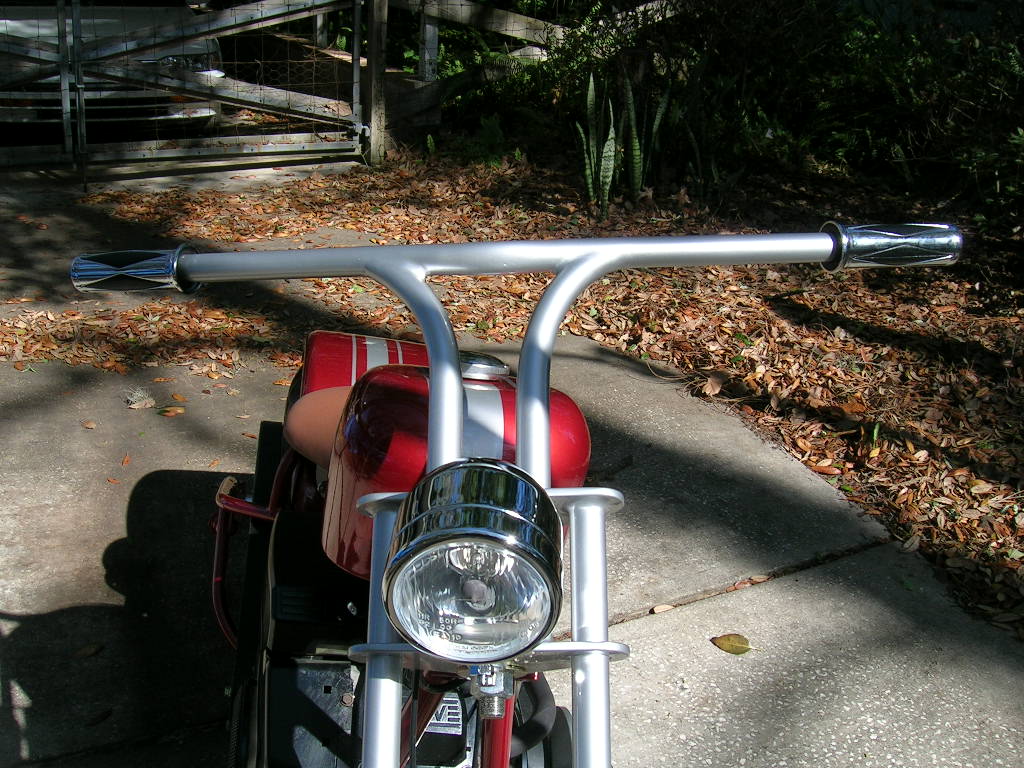
The handle bars were another item where no build
pics were taken, they just sort of got made quickly. Figuring out the internal
throttle took some time, but we finally got it. Then the seat and battery tray
were made. The kickstand, brake pedal, master cylinder mount and caliper mount
were also made. At this time the switch box and brake light were also
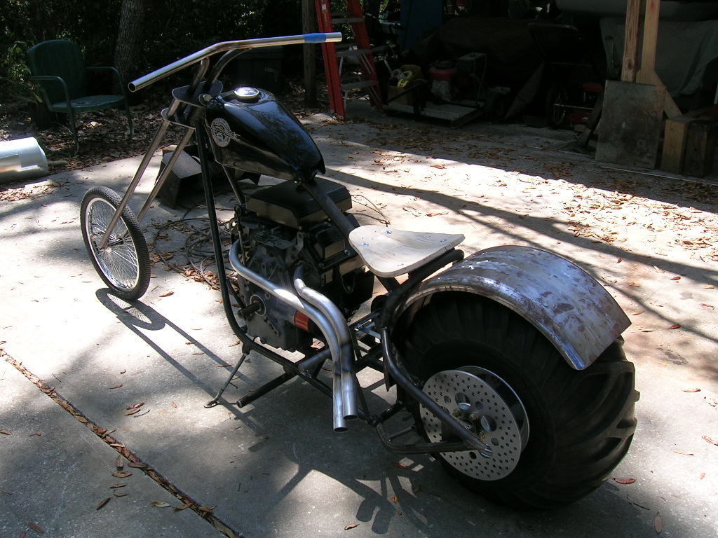
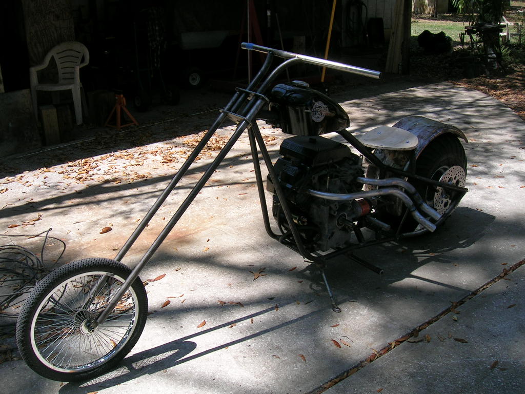
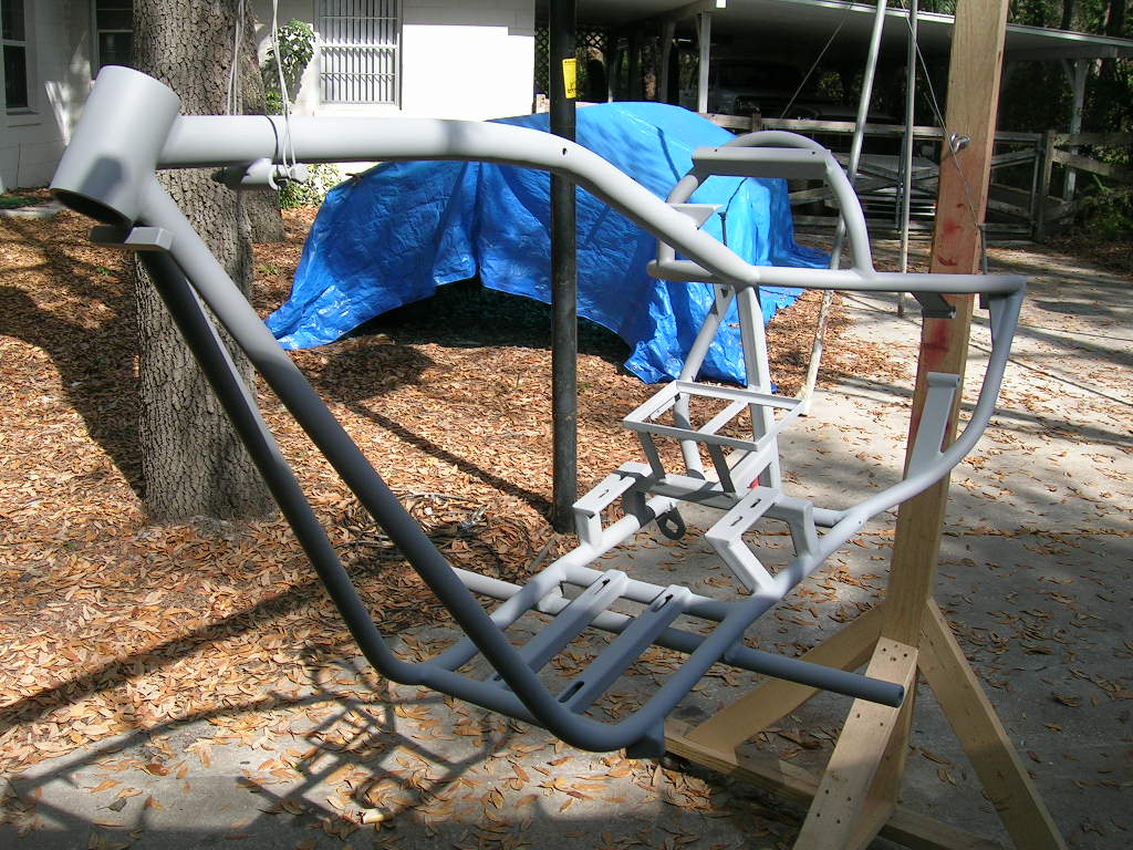
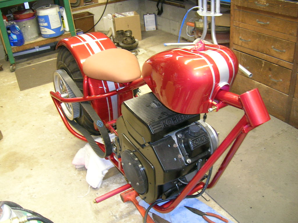
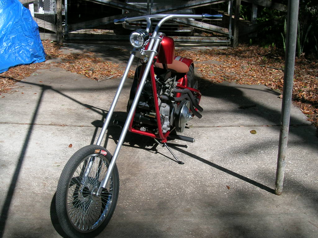
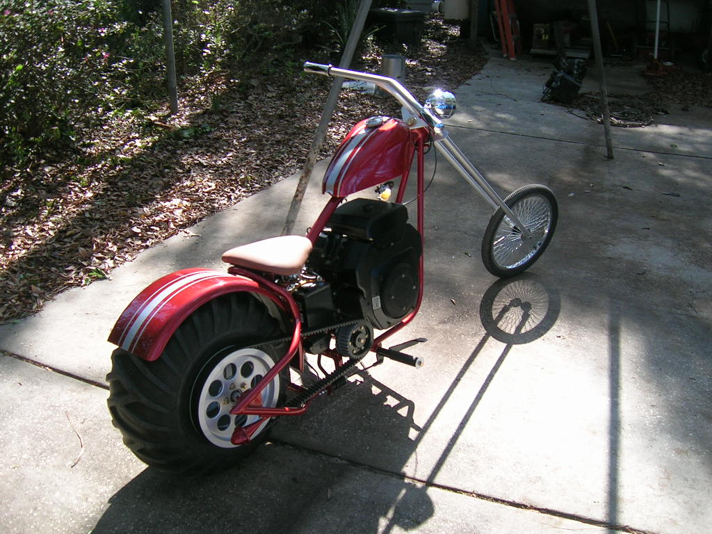
constructed. At the end of March, the bike looked something like this:
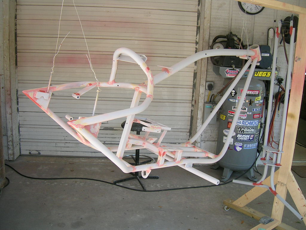
Now it needed to be disassembled and welded fully.
Luckily we only had one minor inconvenience from weld warping which was on the
triple clamps. Some shaving of a bearing race solved the problem. Lots of
sanding the weld beads and slag off produced a very shinny frame for which it
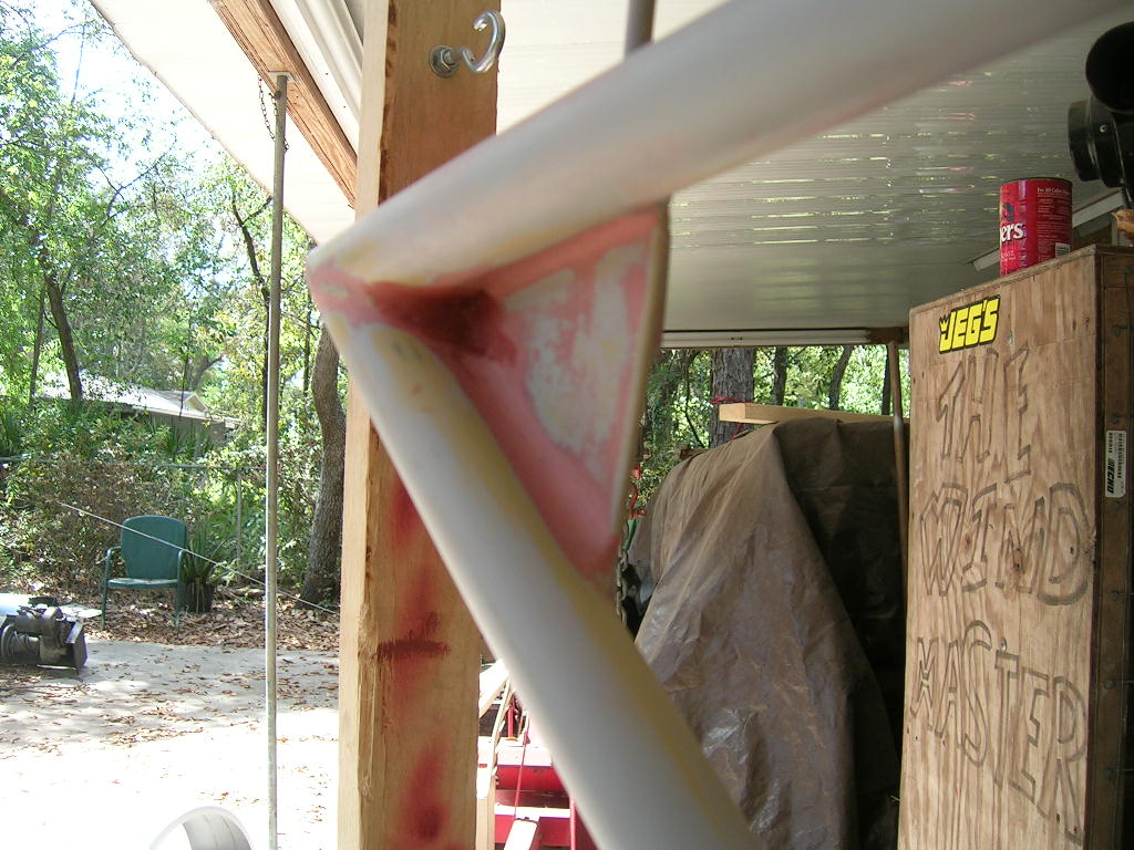
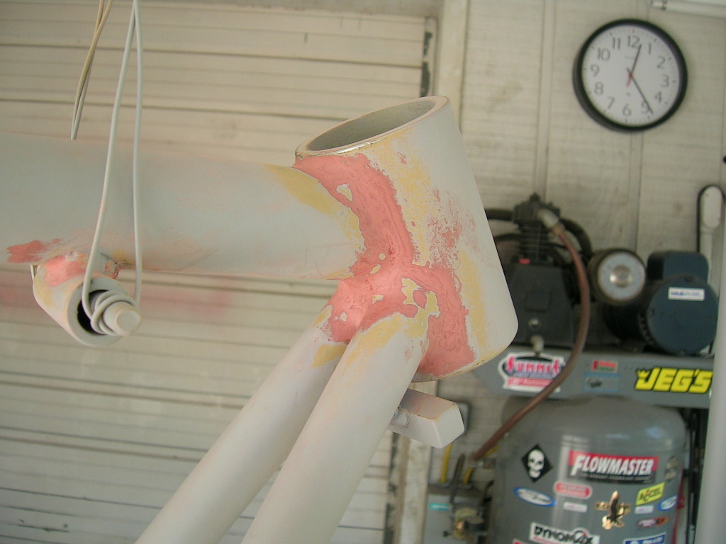
was ready for yellow DuPont Vari-Prime primer. Next went on a grey coat of
primer sealer. After that a few days worth of puttying took care of any
unsightly weld joints/seams:
Another coat of grey primer sealer to hide any
orange putty was applied:
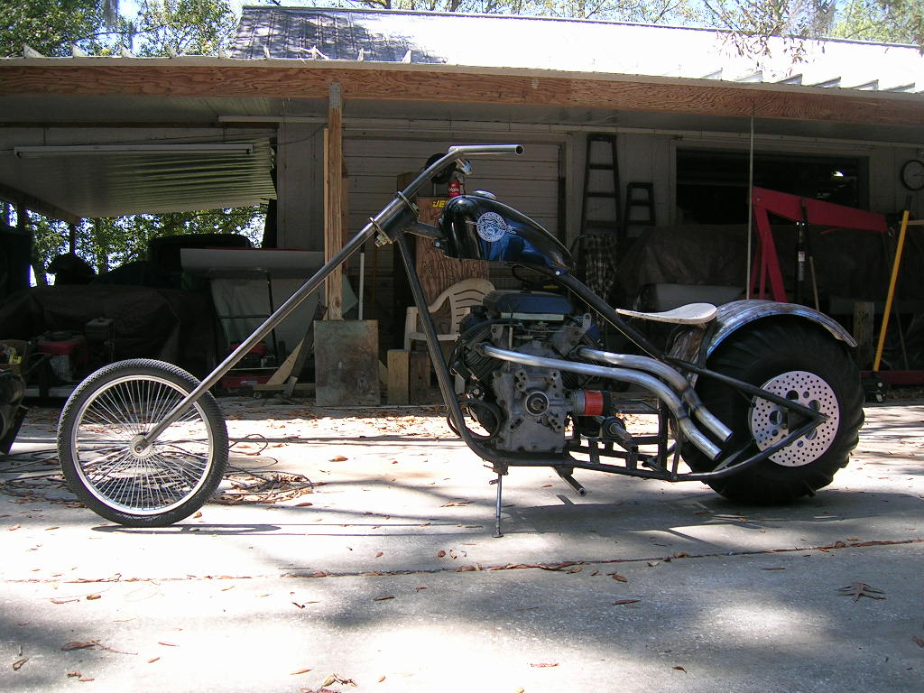
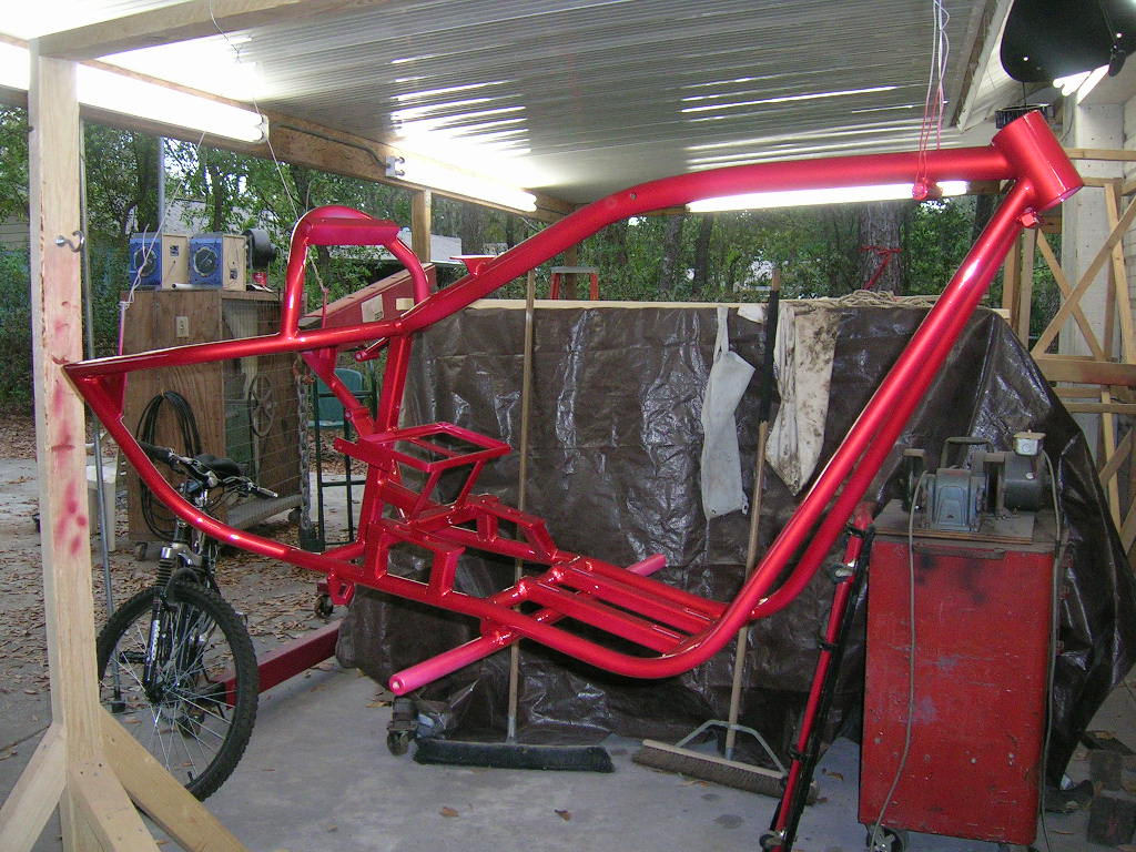
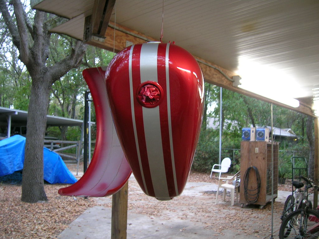
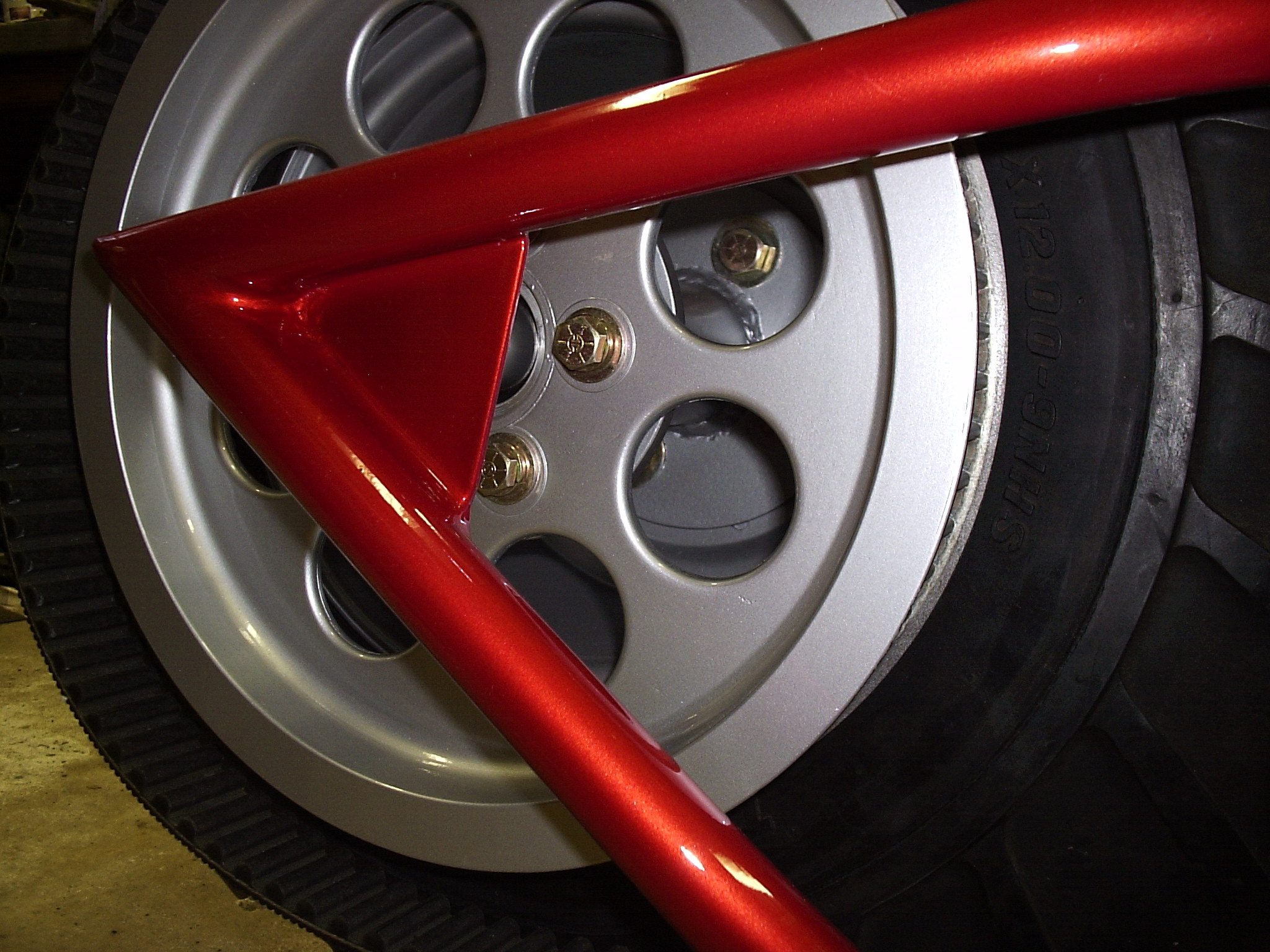
For the color, we used some DuPont Chroma-Base
basecoat/clearcoat which we had left over from painting an F-150. My girlfriend
suggested giving the bike some added colors in the form of some simple pin
striping. I never doubted her and the results speak for themselves. Painting
took two weeks as the weather in FL is hit or miss. One day it was cool and
breezy, the next it was hot and humid, all in the first week of April!
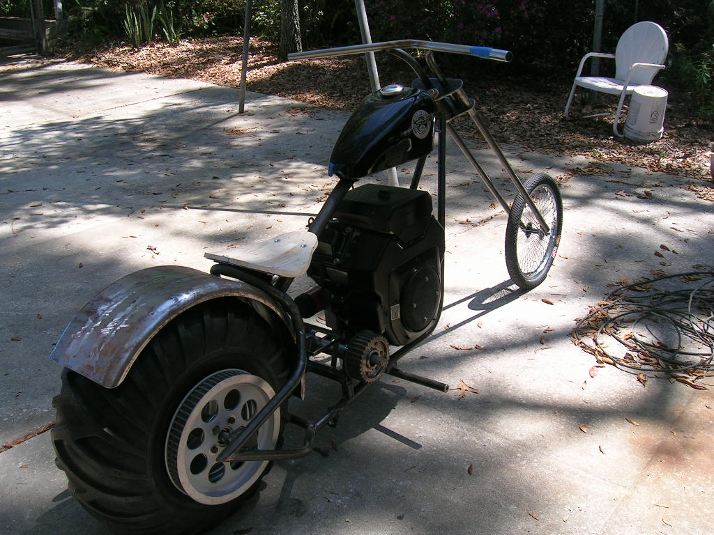
After the clearcoat was finally hard, re-assembly of
the bike could now begin. Everything went back together very smoothly, an
outcome that was expected from a four week build- measure more than twice, cut
once and tack weld twice:
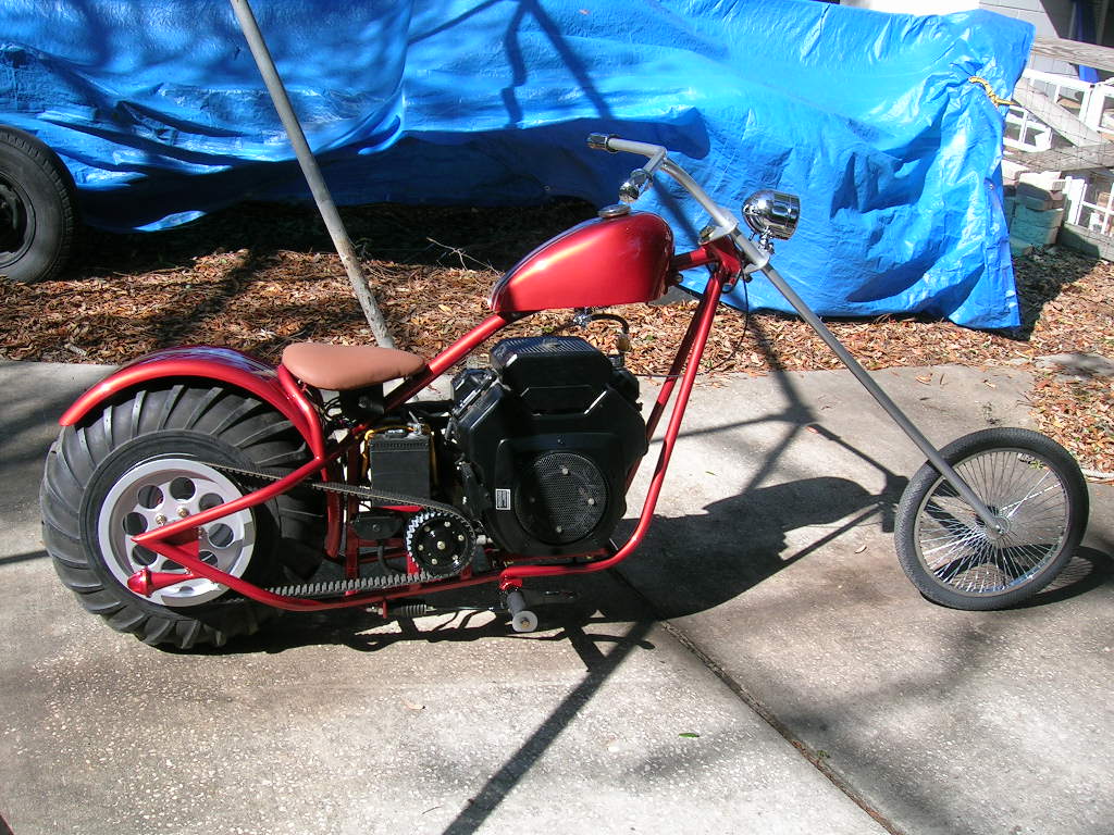
Within minutes after completing the reassembly, gas
and oil were added and the Kohler came to life with a mean rumble emitting from
the straight pipes. After it warmed up, I twisted the throttle and the 94C
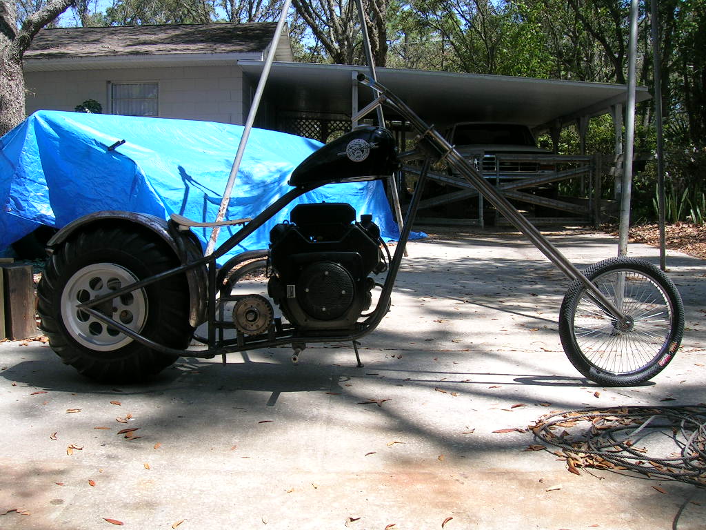
clutch grabbed the belt and away I went.
After completing this project, I would say it has
been the best and most satisfying project done yet. I couldn’t have done it
without the help of my dad and girlfriend.
The bike performs exactly as I expected it to. I’ve never ridden a Harley or
custom before but I must say it does feel like a “big bike”. I’ve definitely had
it up to 50mph and it was begging for more but the lack of road prevented me
from “testing its limits”. The Kohler has so much torque it’s unlike anything
else I’ve ever ridden. It wasn’t this much of a thrill when it was on the go
kart due to obvious reasons. The rumbling V-Twin still gives me goose bumps when
I first mount the bike. The bike is plenty fast the way it is so I would be a
fool to remove the governor.