This page will be entirely devoted to the rebuild of the Dana 70 rear along
with the addition of our rear disc conversion. Using the same parts the
Sterling axle received six years earlier
(almost to the exact day), we pretty much knew what to expect this time around. We
also left the whole axle behind not bothering to buy it just for the tube
flanges. Even with friends who own a machine shop, this still was entirely too
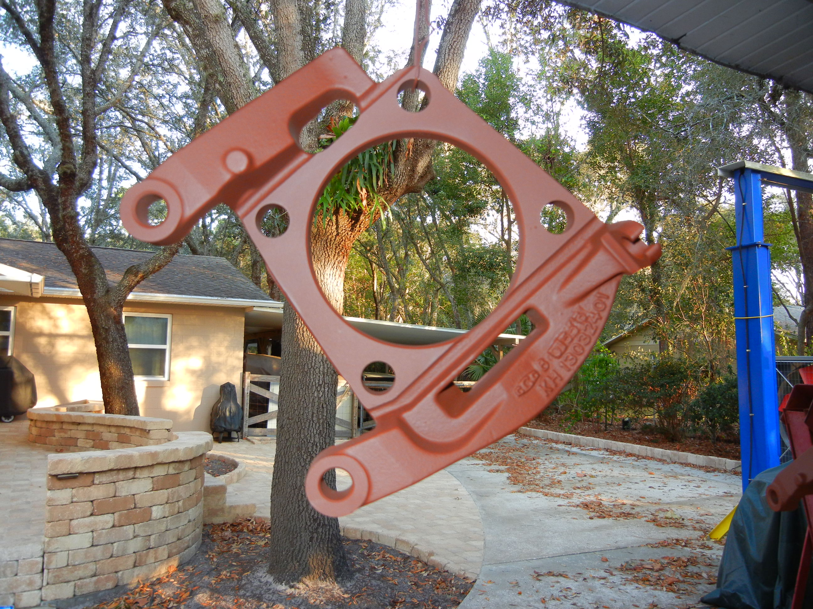
much work to justify saving the original tube flanges. I instead decided to have a set
laser cut from 1/2" plate steel. After much careful measuring, here is a
CAD sheet showing what my new
flanges look like. During the first conversion I did not sketch this out after
removing them from the van's D60 axle and regret not doing so after being flooded with
requests on a monthly basis. Well here is your chance to duplicate again what we
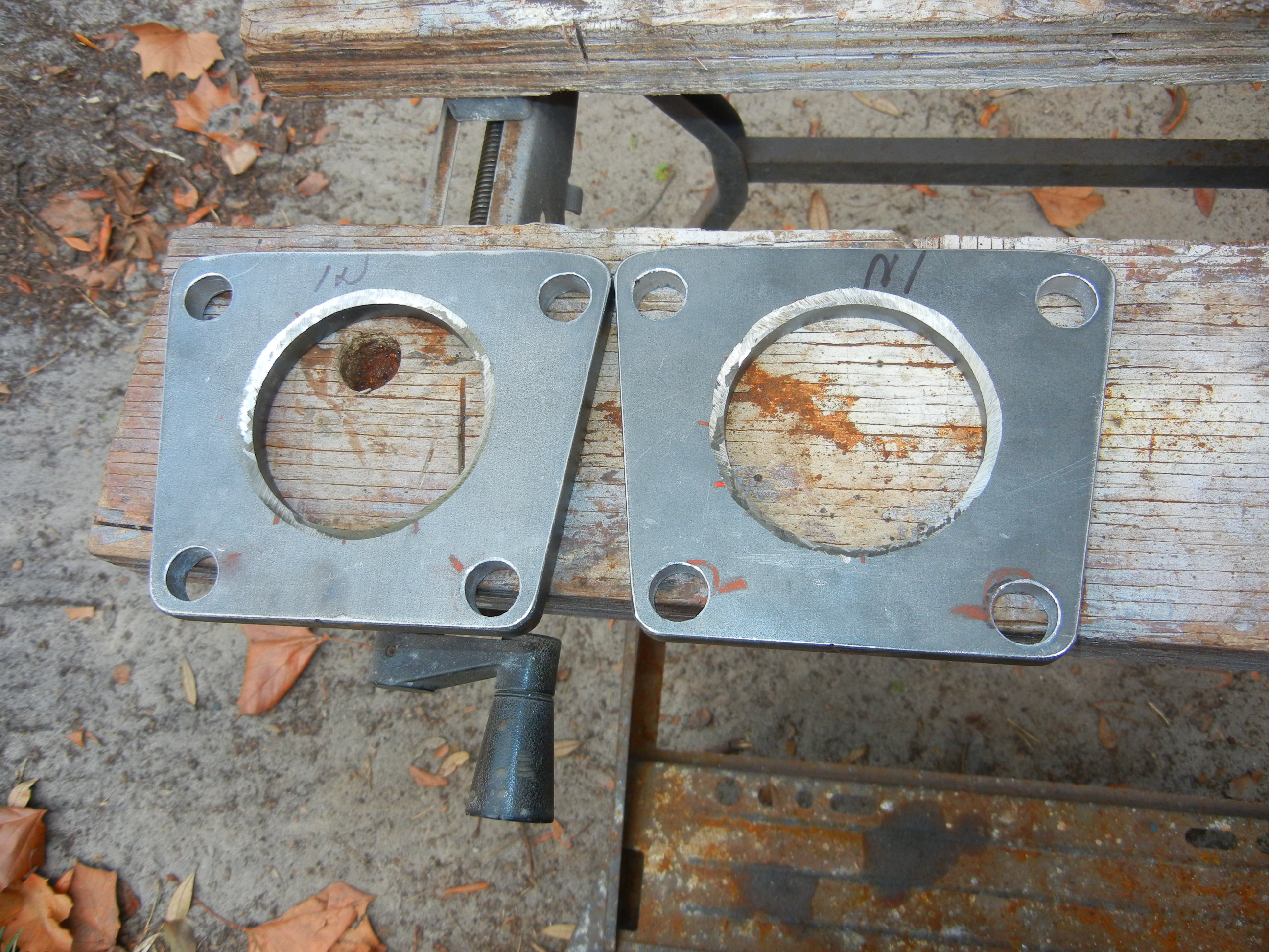
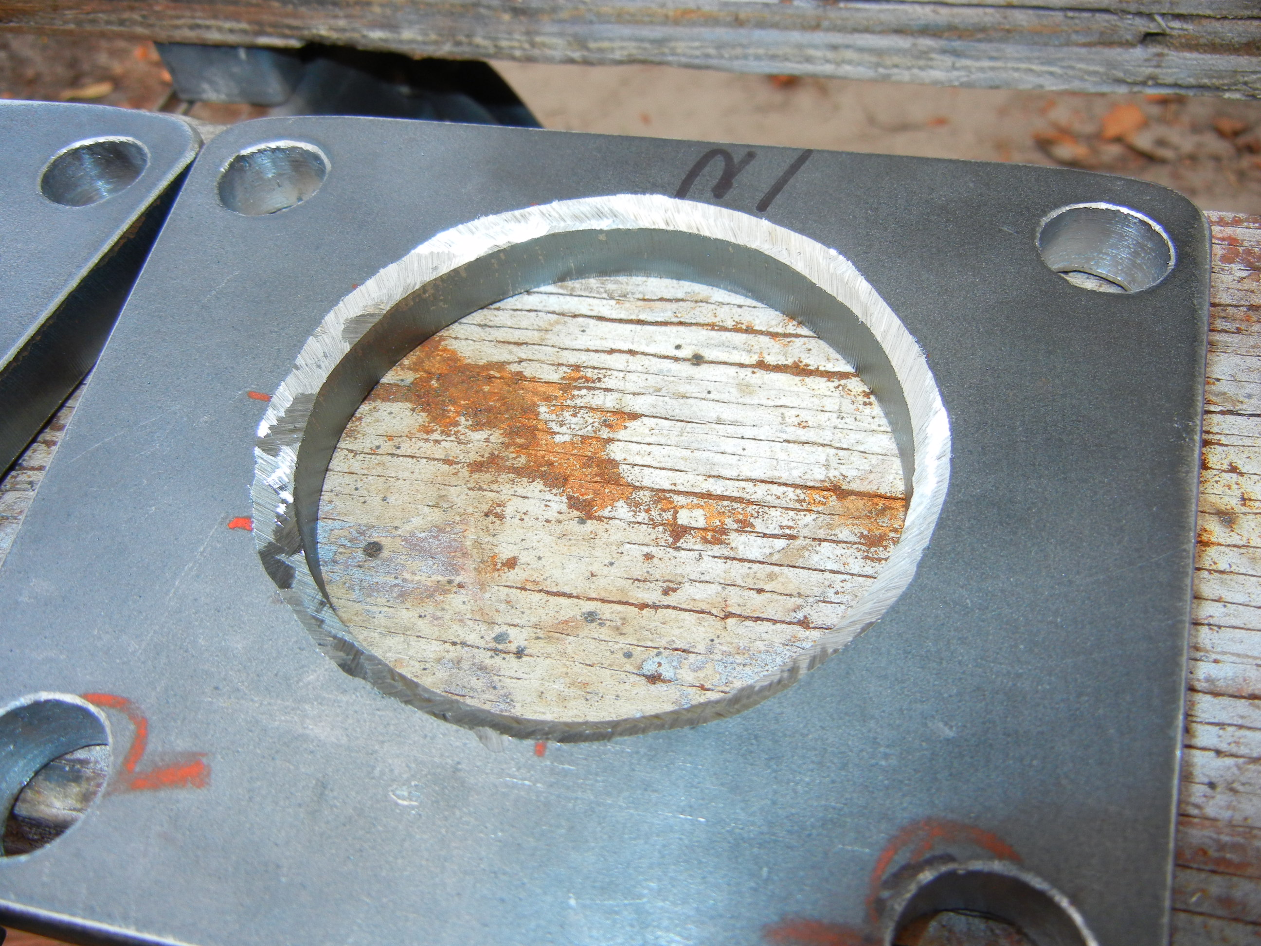
have done. Remember I am showing a small inner hole since the D70 tube necks
down. The Sterlings, 14bolts, D80's and other D70's do not neck down so you will
need to determine your own hole diameter! So enjoy and as always, I do not take responsibility if your custom
made flanges do not fit your application!
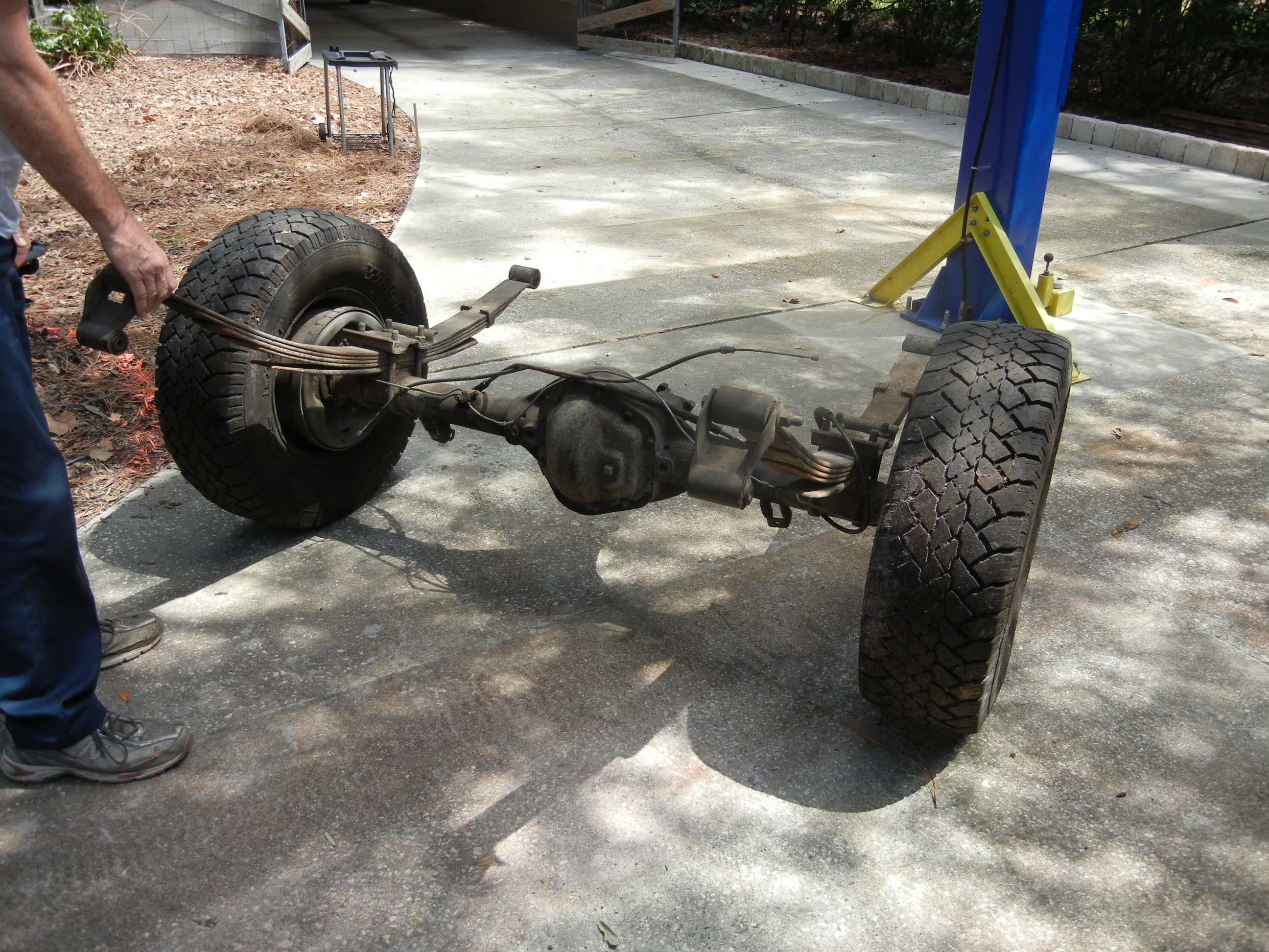
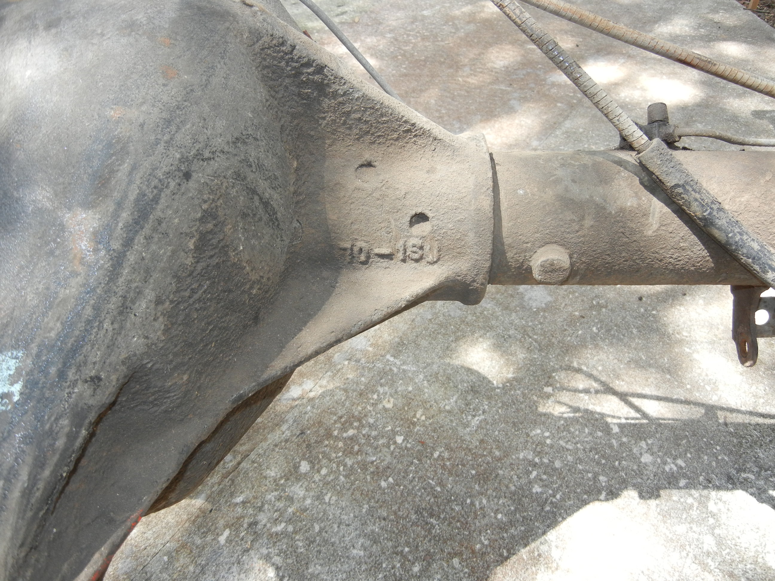
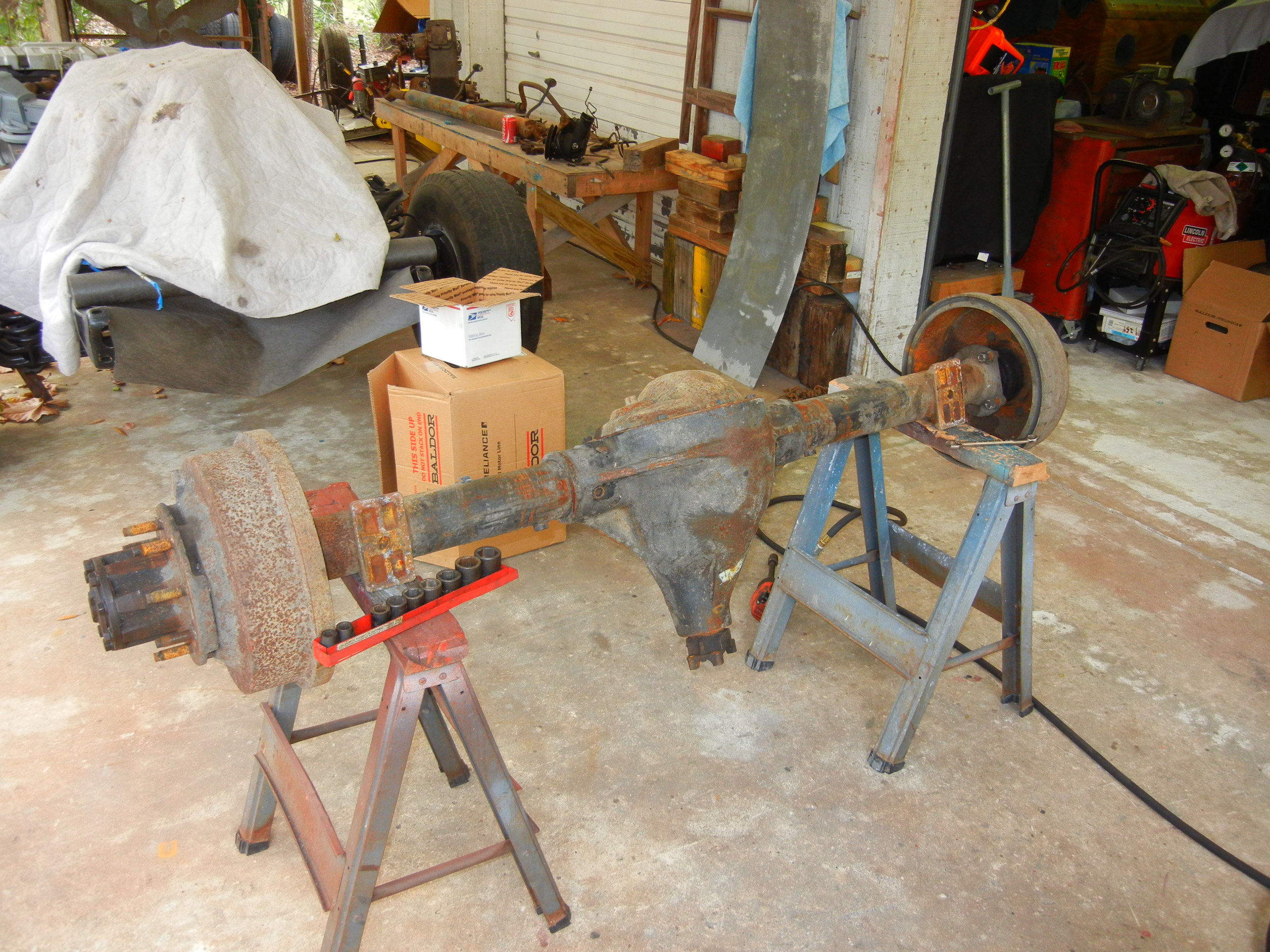
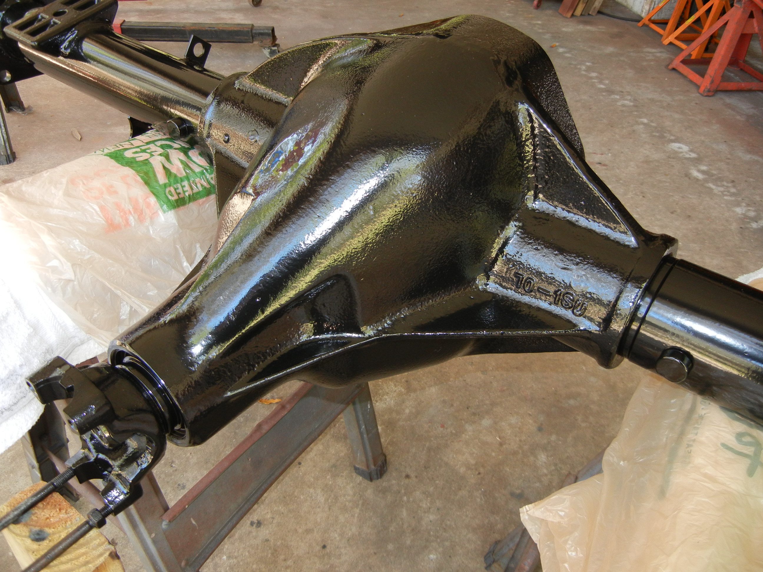
As previously stated, this axle came from a 1984-85 F-250 2wd with a diesel
engine. It was one of the last models before Ford chose to use the Sterlings
starting in 1985. It is the "U" model with 1.5" and 35 spline shafts. According
to the BOM it had 3.54 gears from the factory but someone swapped in 4.10 gears
later on. I wasn't planning on keeping then anyway, especially after I found out
they were chipped! 4.88 gears along with a new carrier will be going in. I will
also use my Powertrax No-Slip I bought for the van.
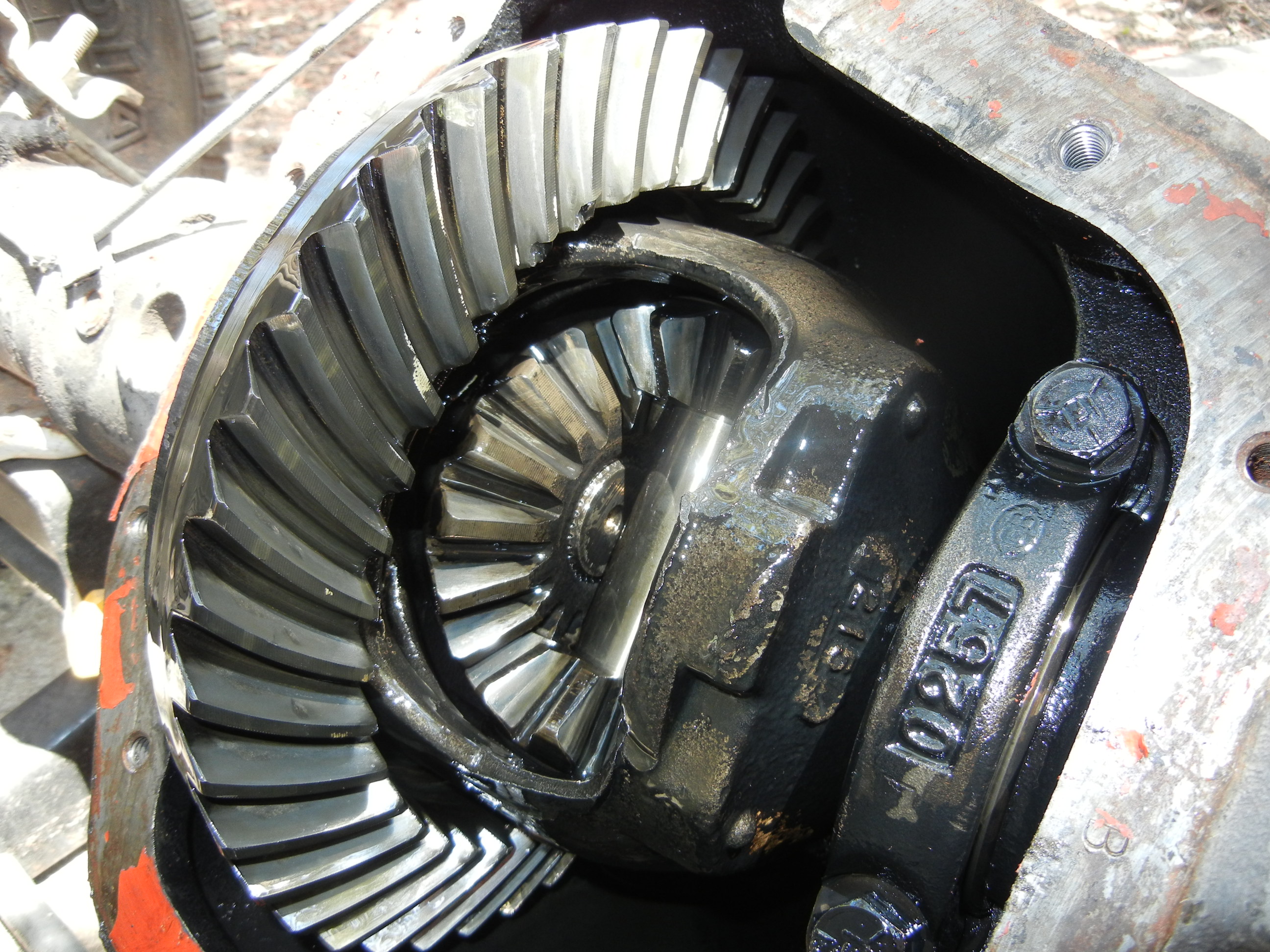
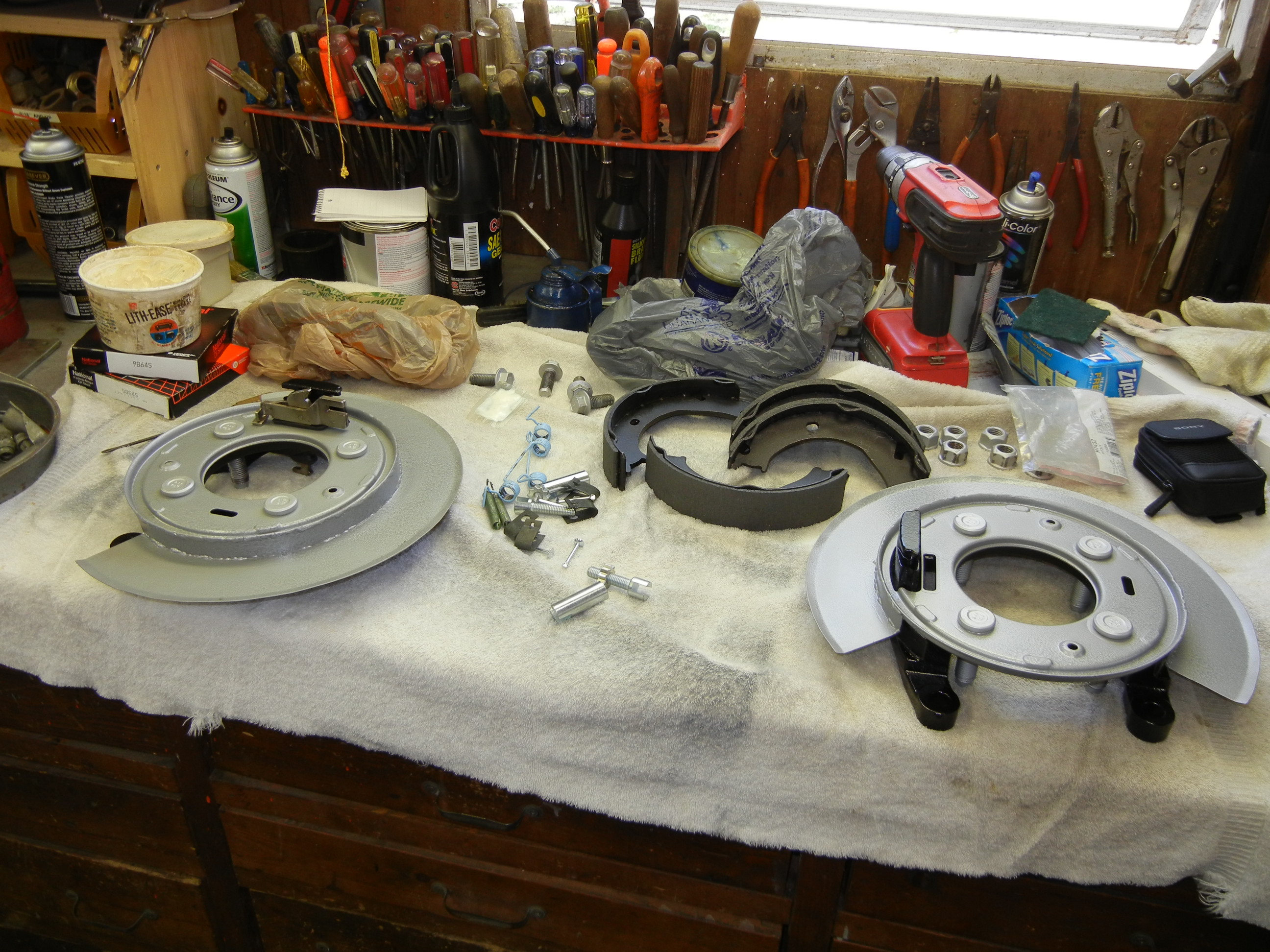
Now on to the rebuild/conversion. Same as before: gather, inspect, clean,
prep, install.
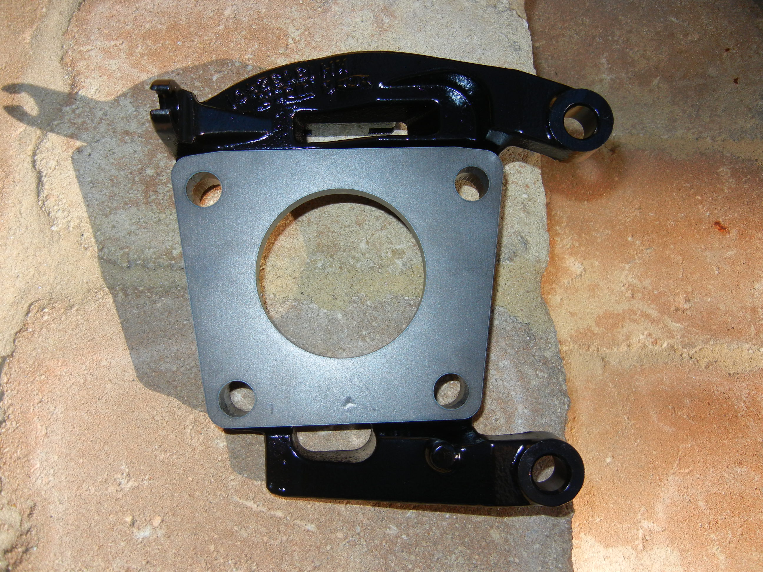
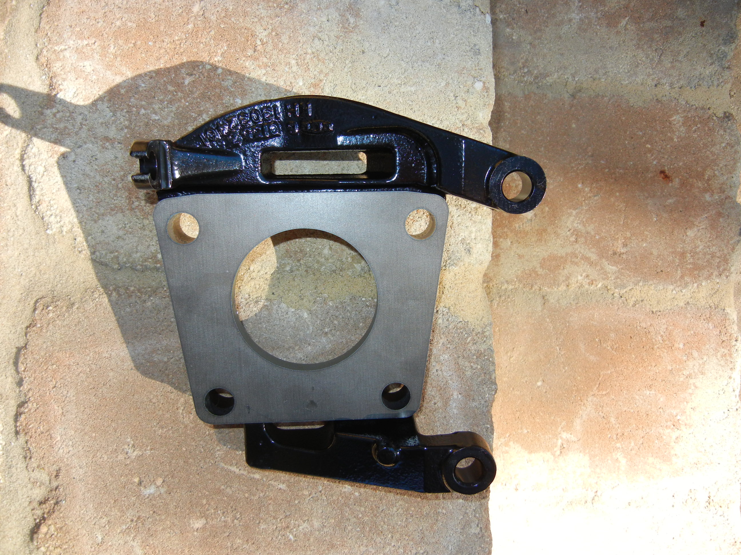
Here are the 2000 E350 brackets:
You'll notice the similar photos to the Sterling page. I am having Deja vu
from six years ago! Where did the time go!?
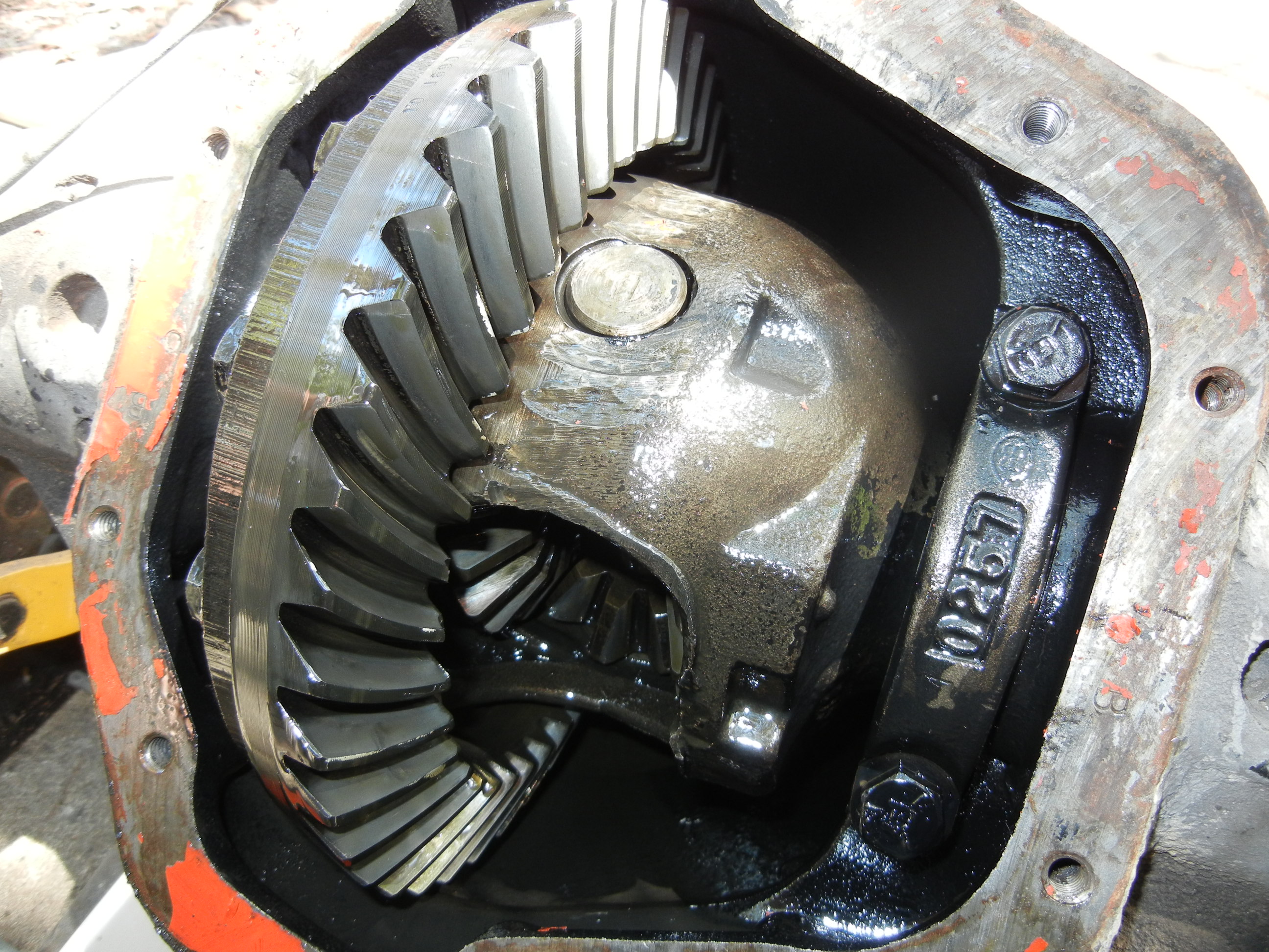
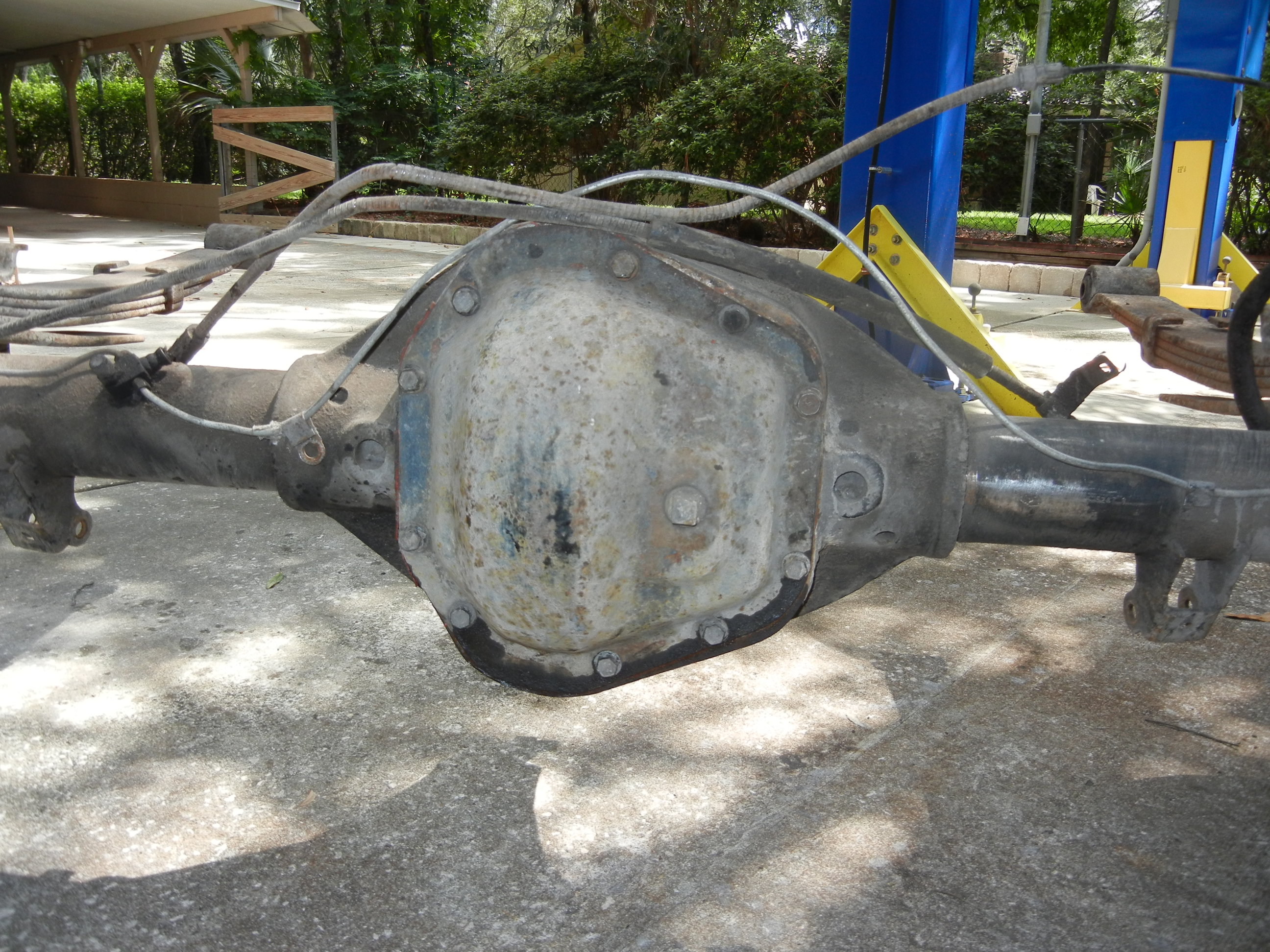
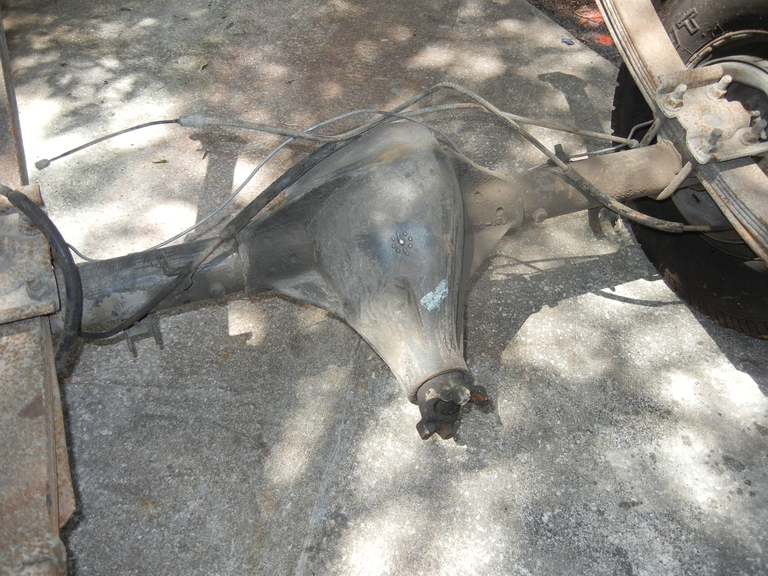
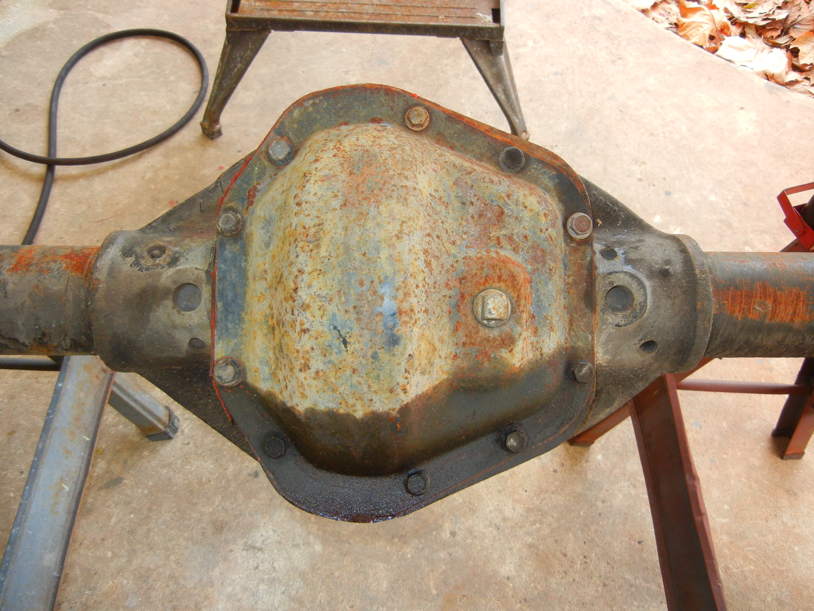
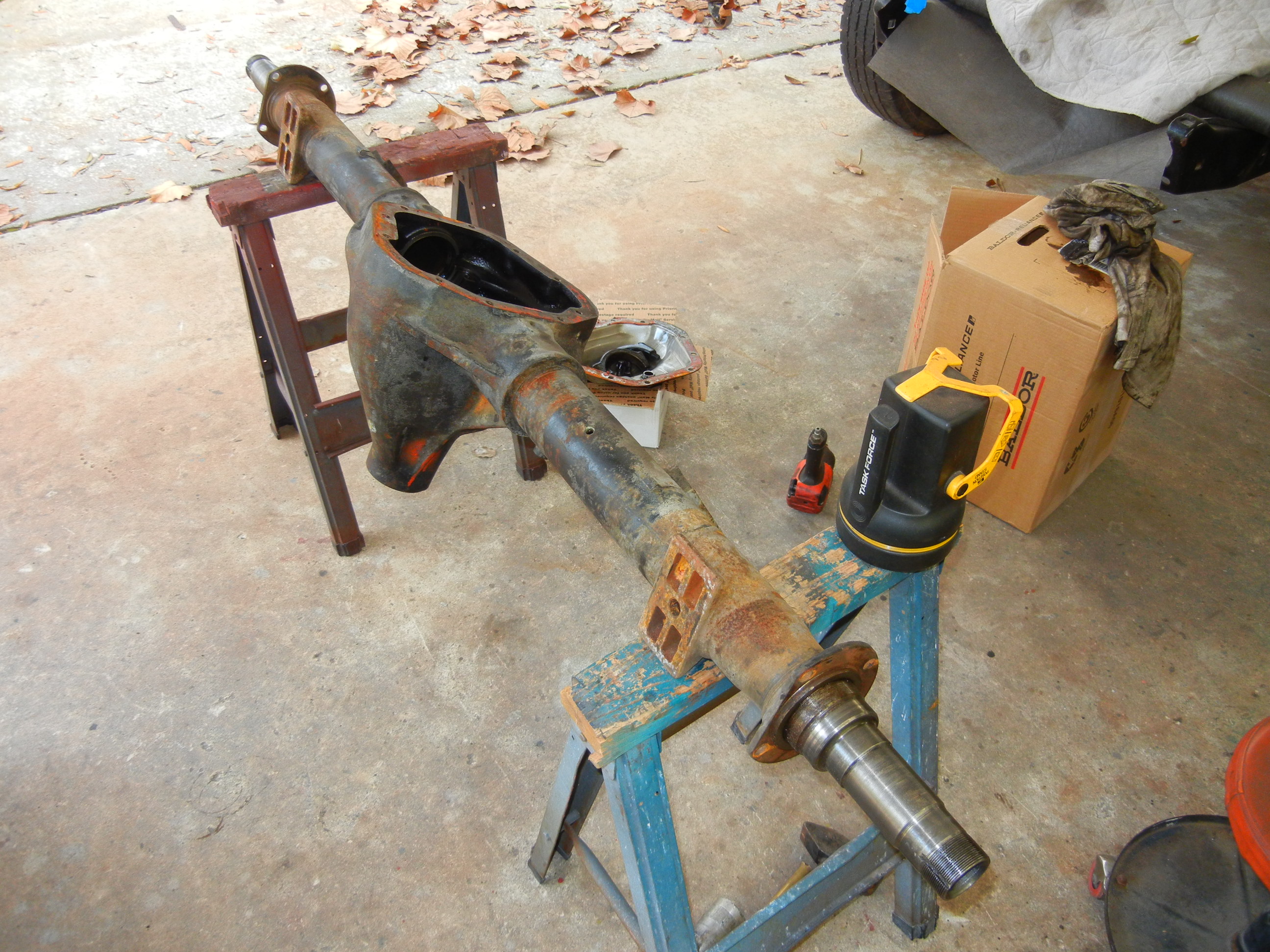
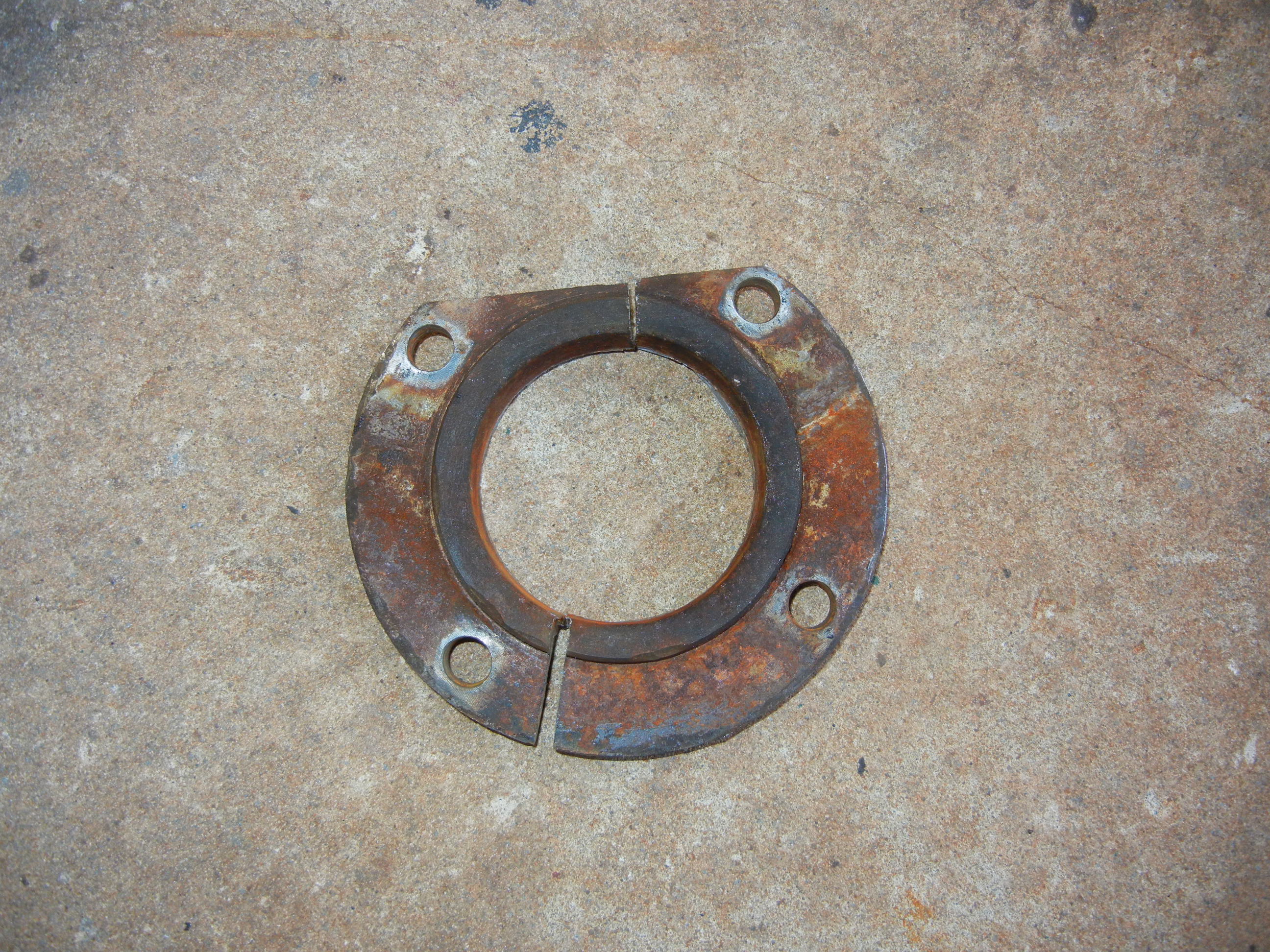
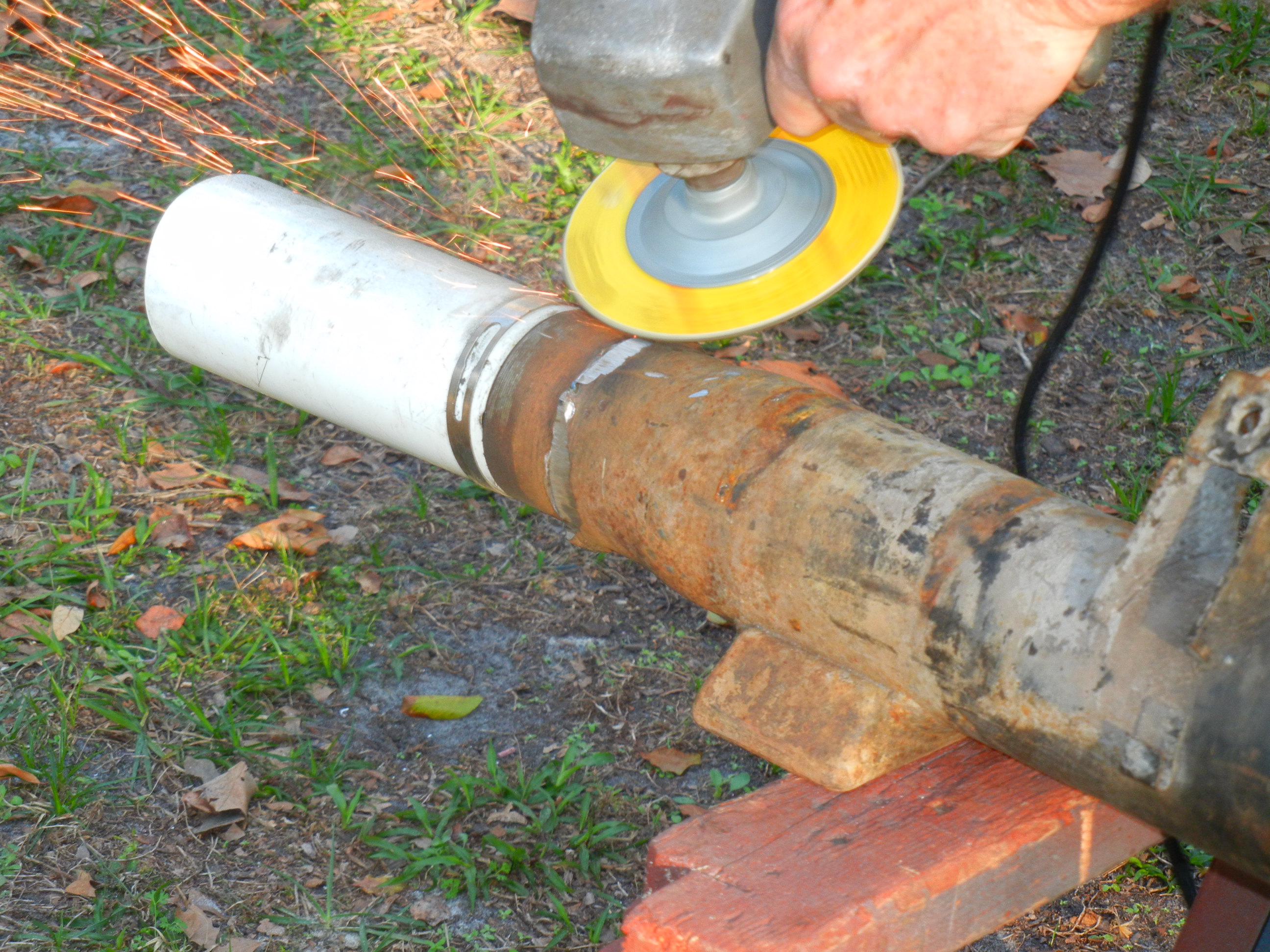
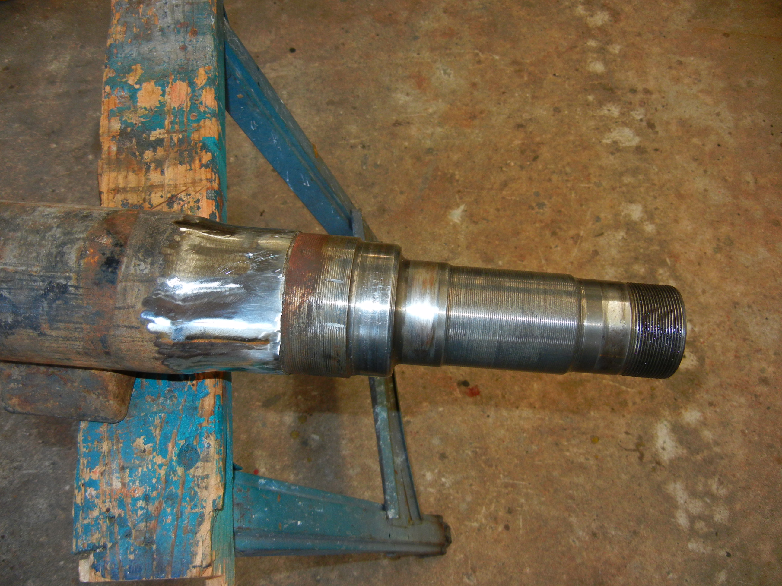
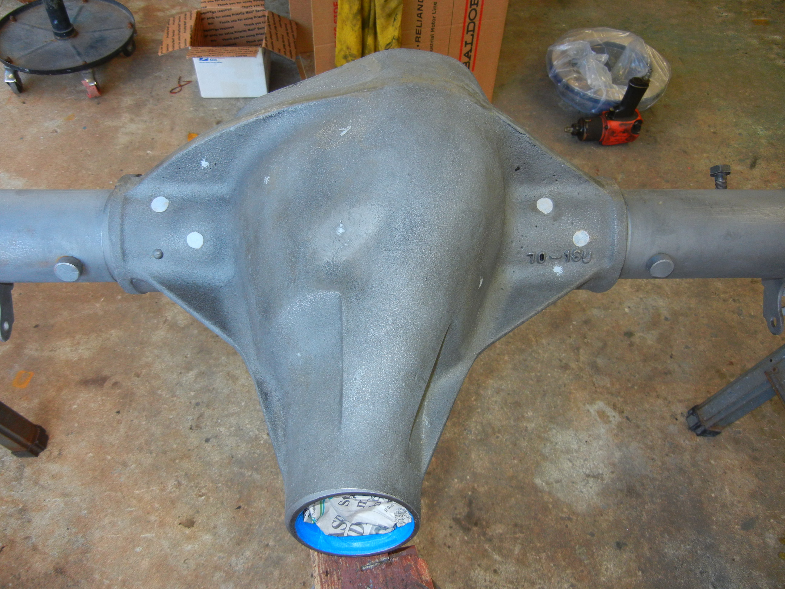
Now you can see this axle has the slight neckdown tubes. It also has a
much better pair of tube flanges welded on which proved way more difficult
to remove than what the Sterling had!
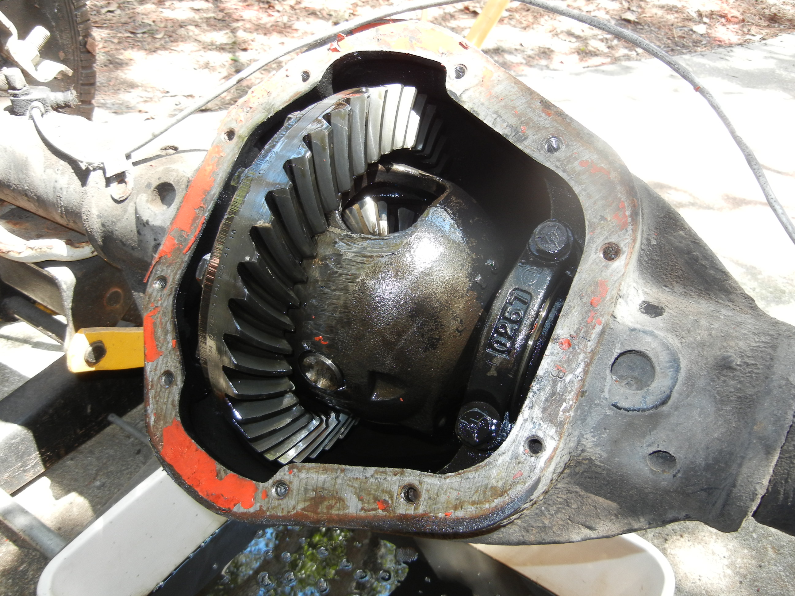
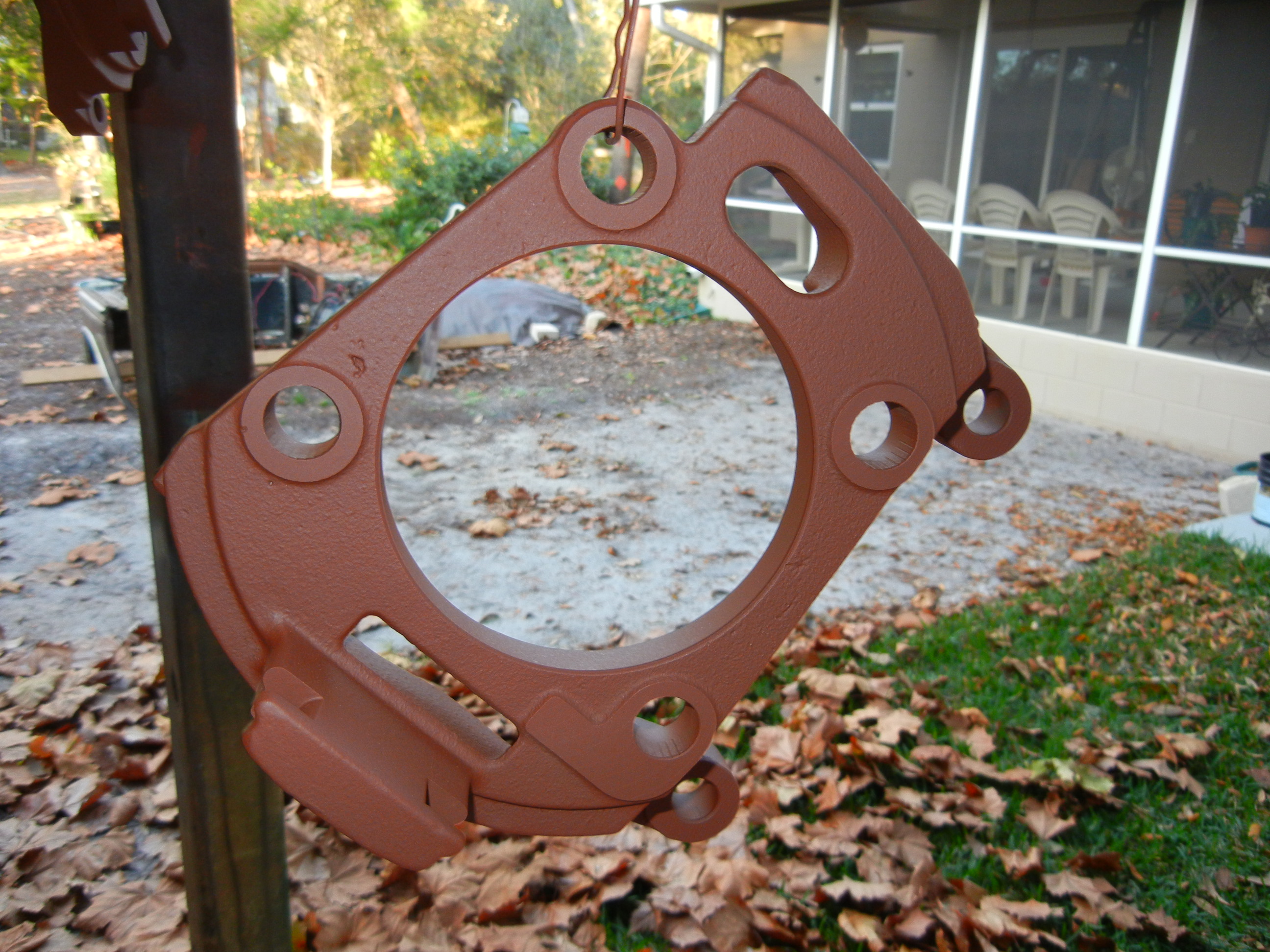
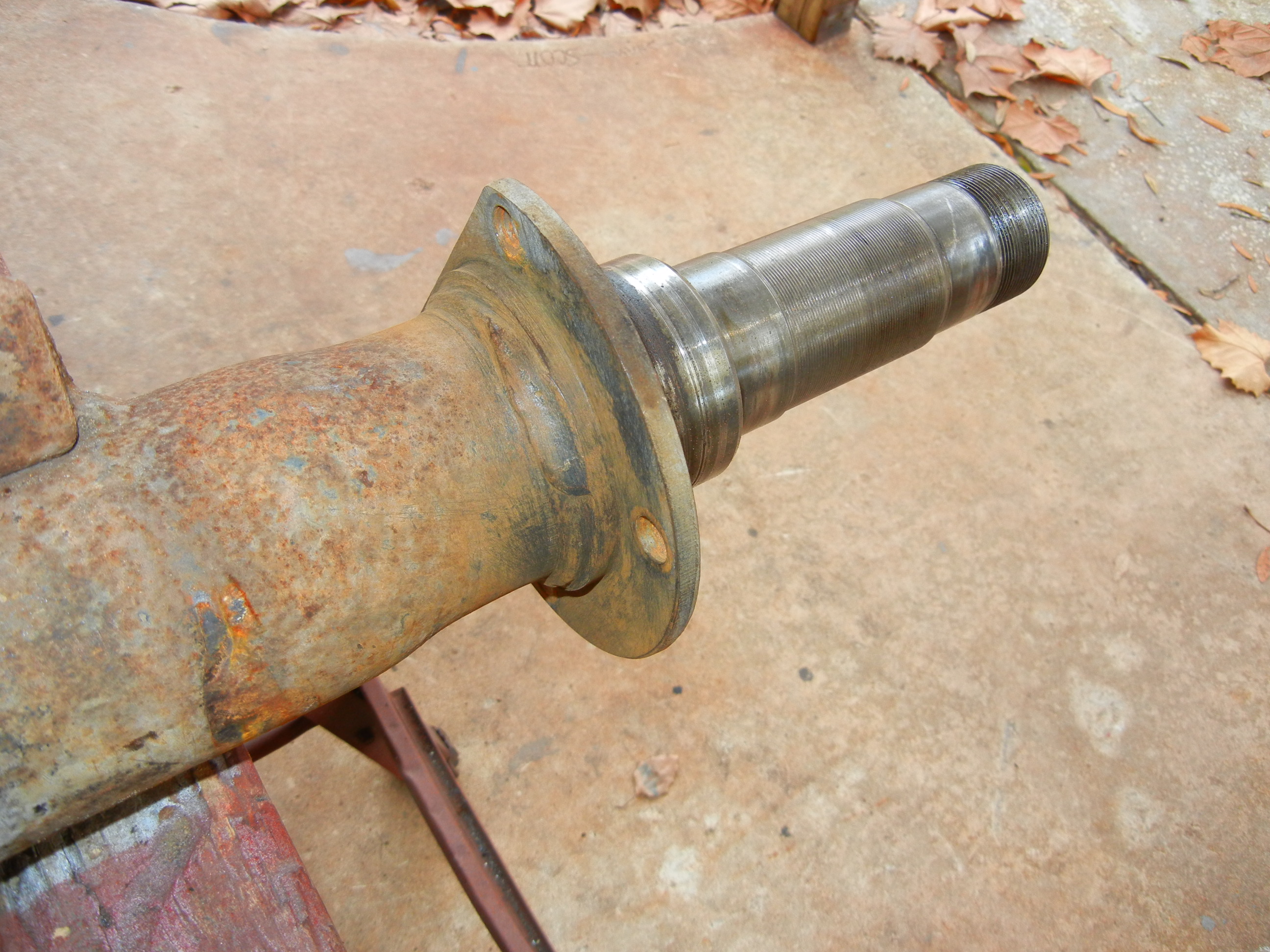
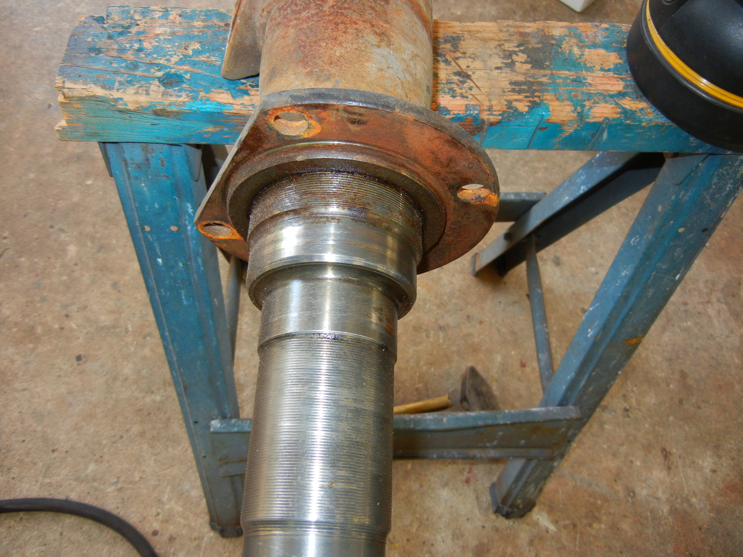
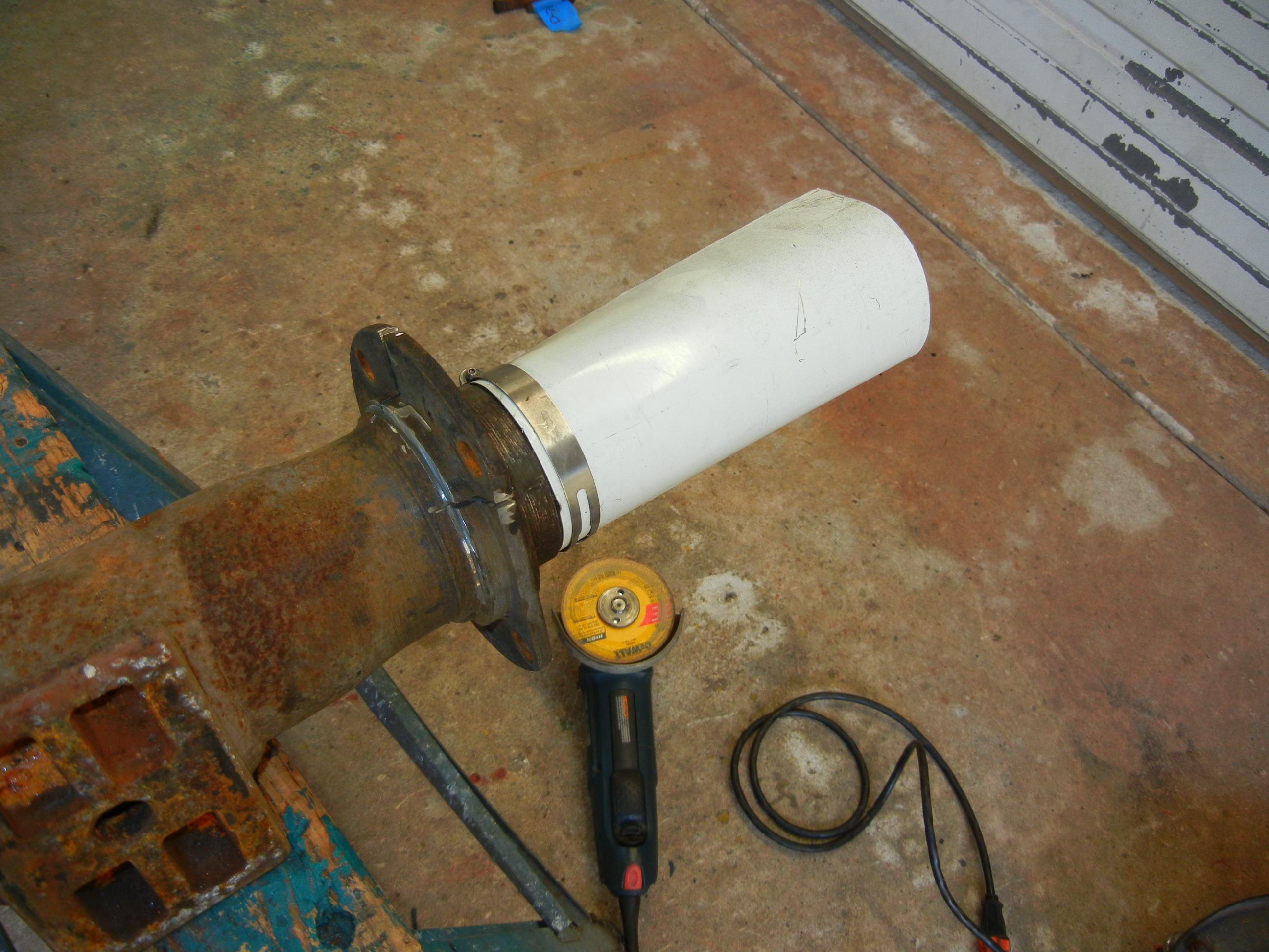
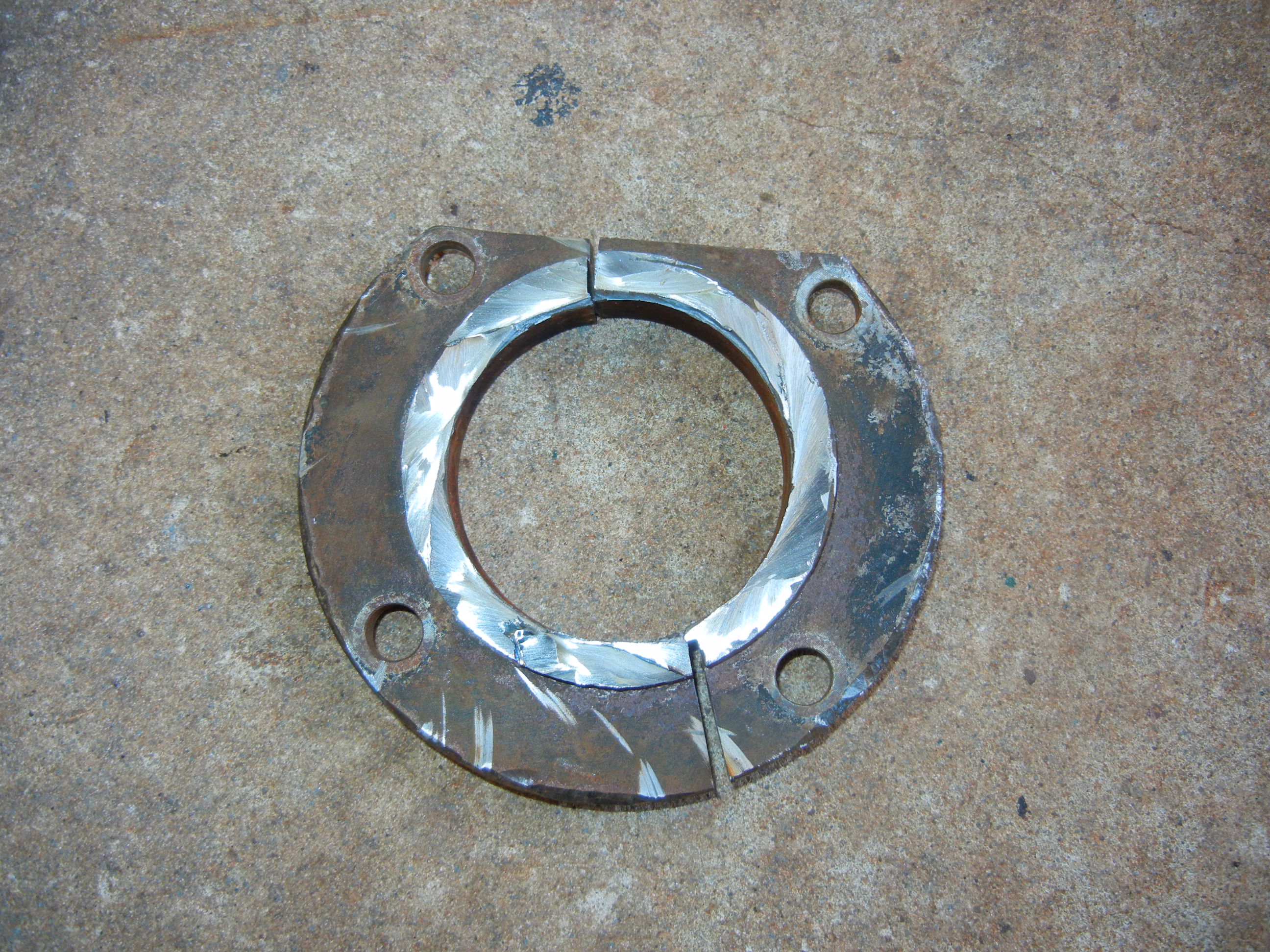
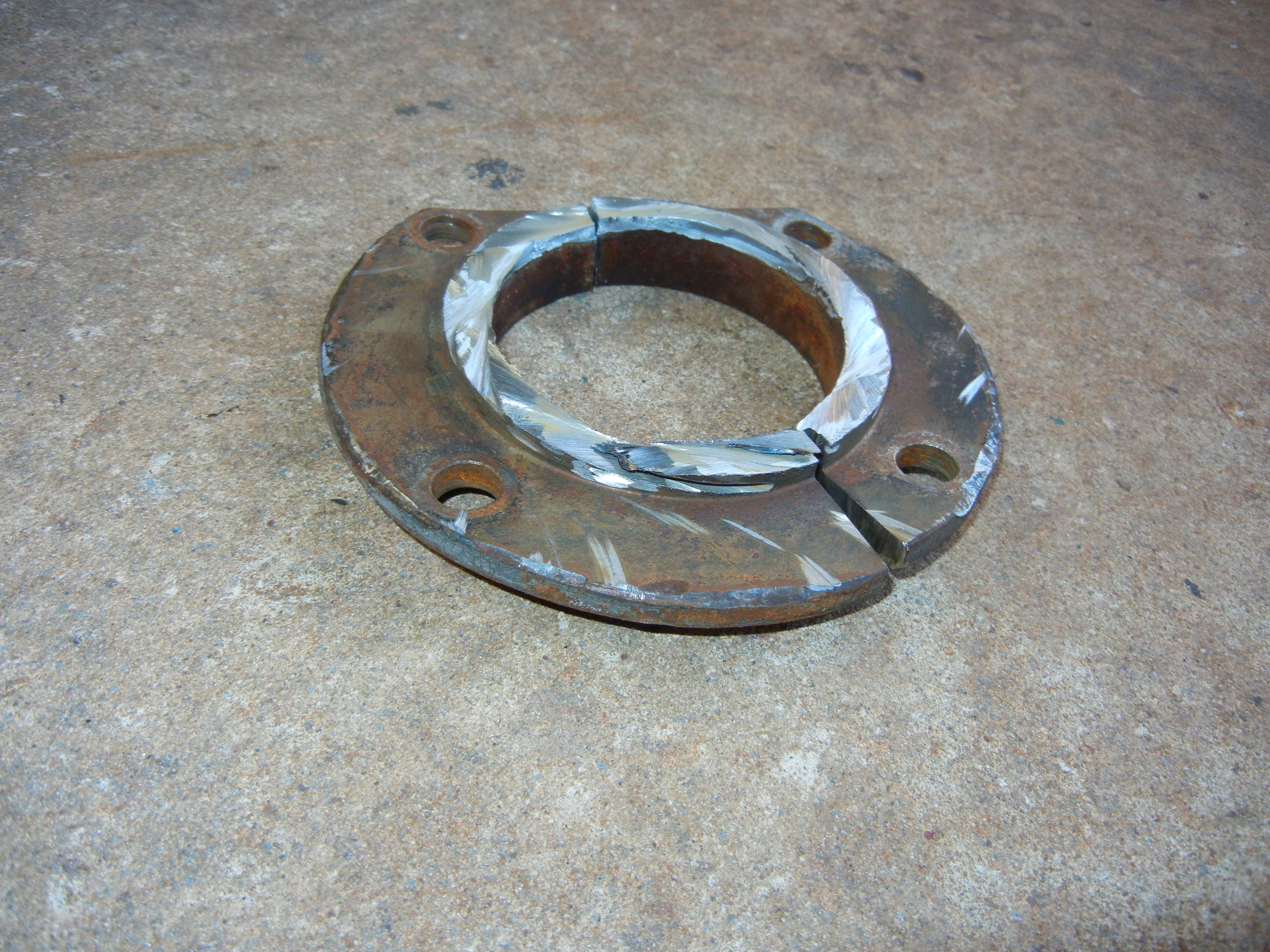
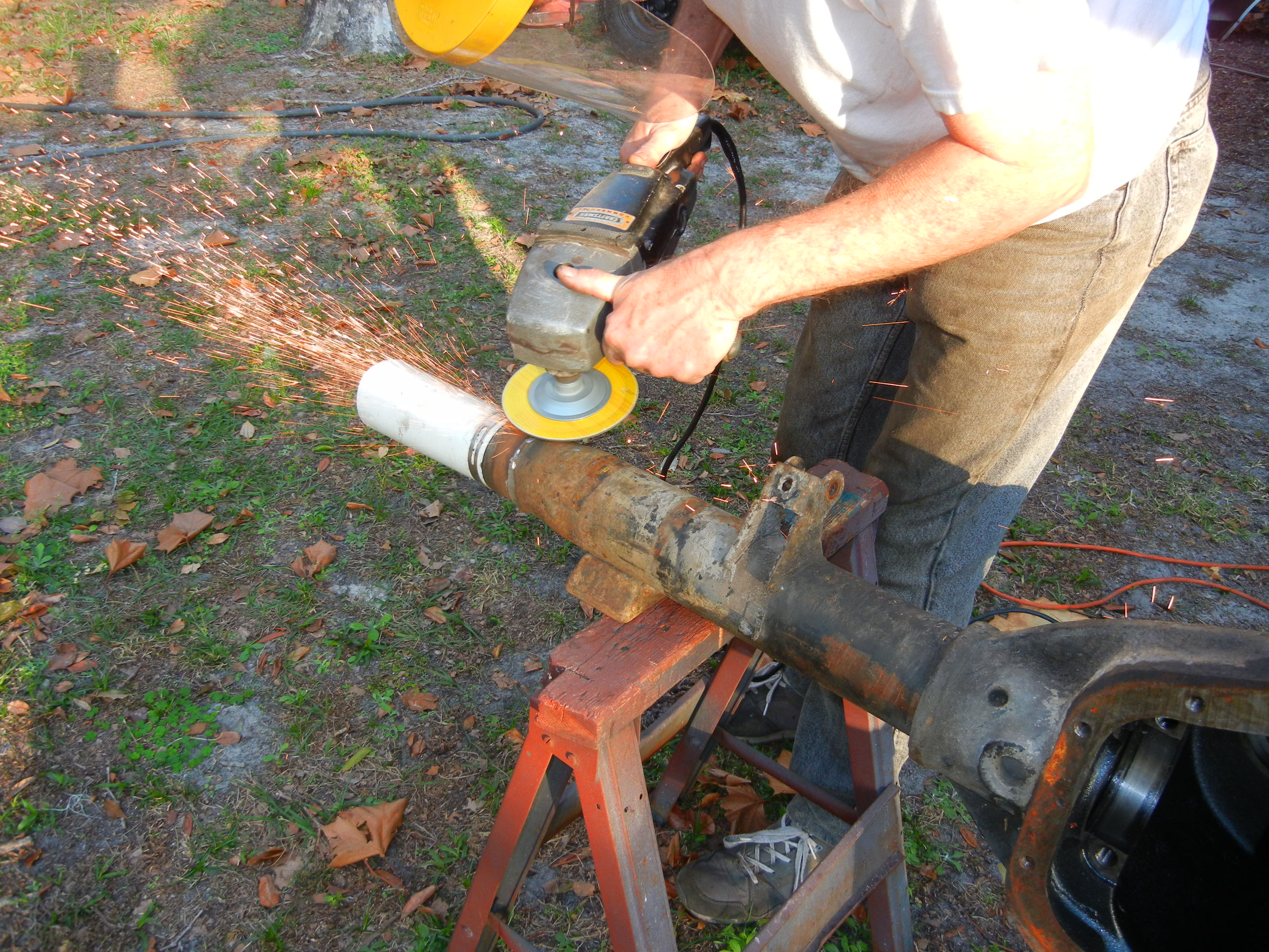
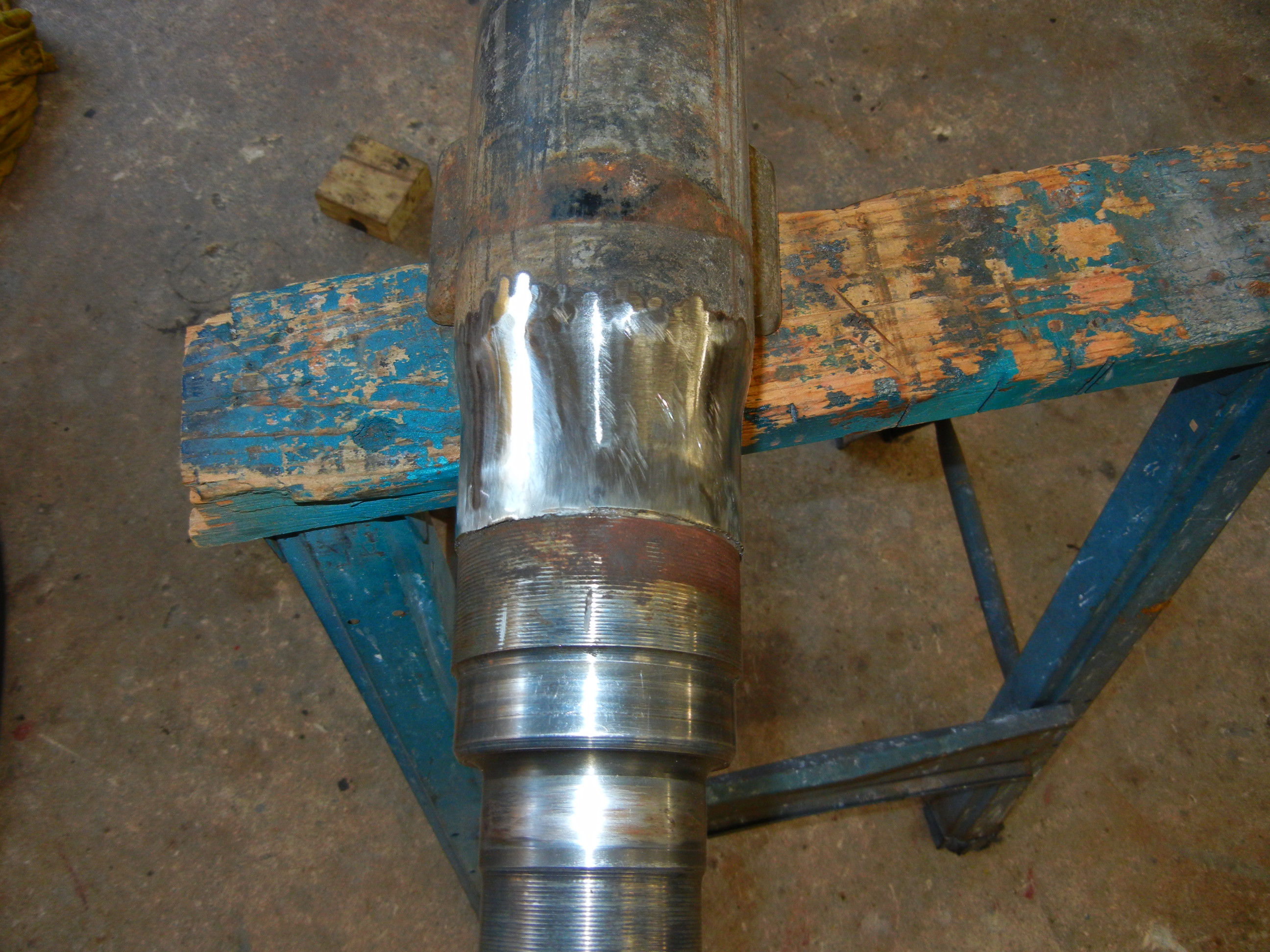
With the flanges now gone, more grinding to clean up the surface for the new
tube flanges. Doesn't this look familiar!?
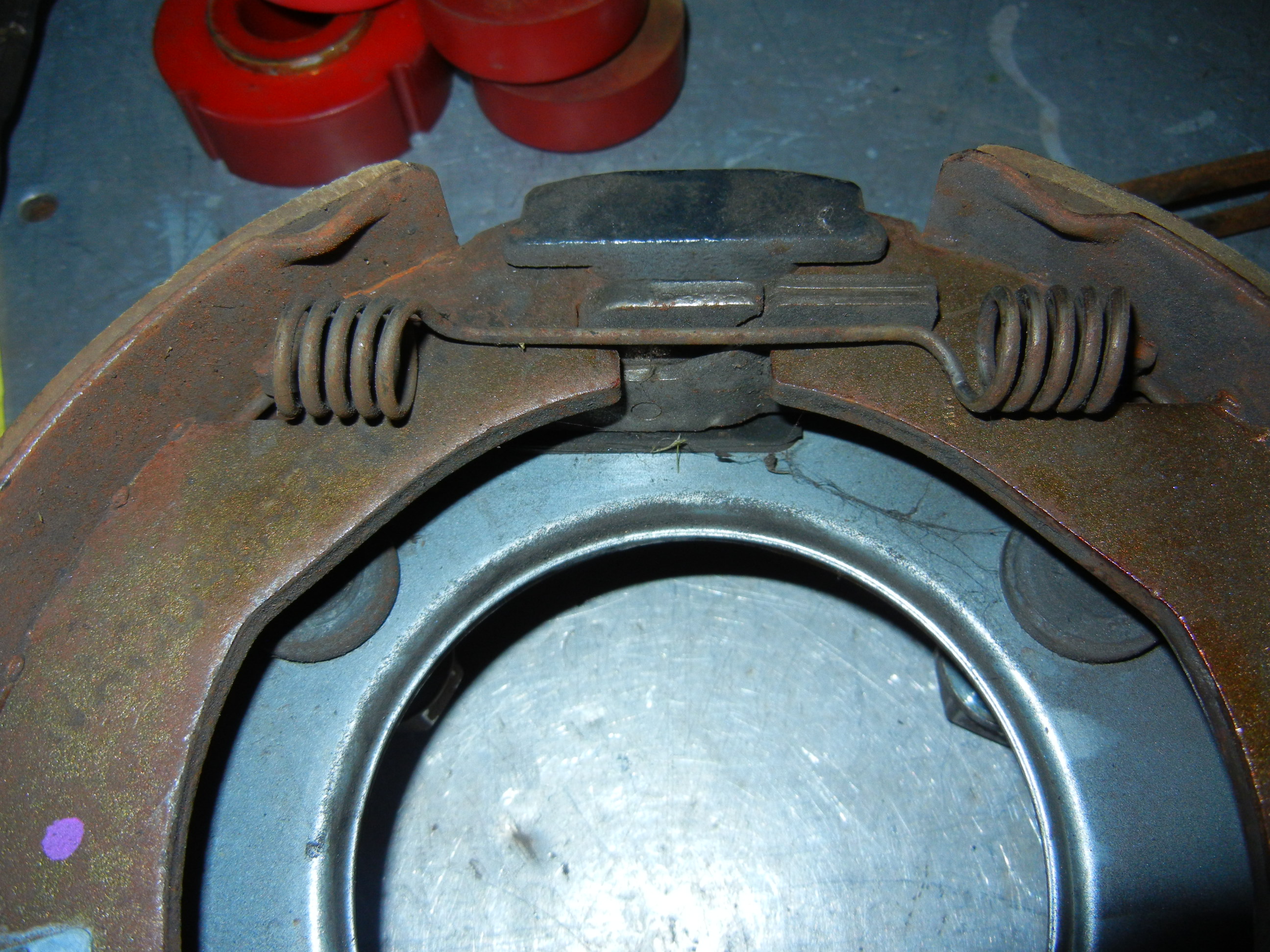
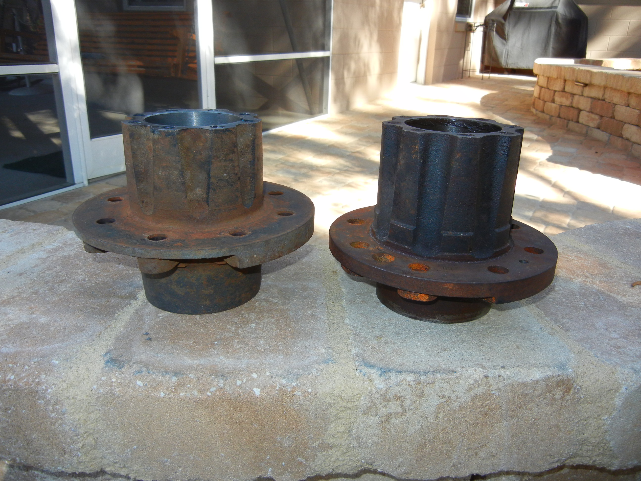
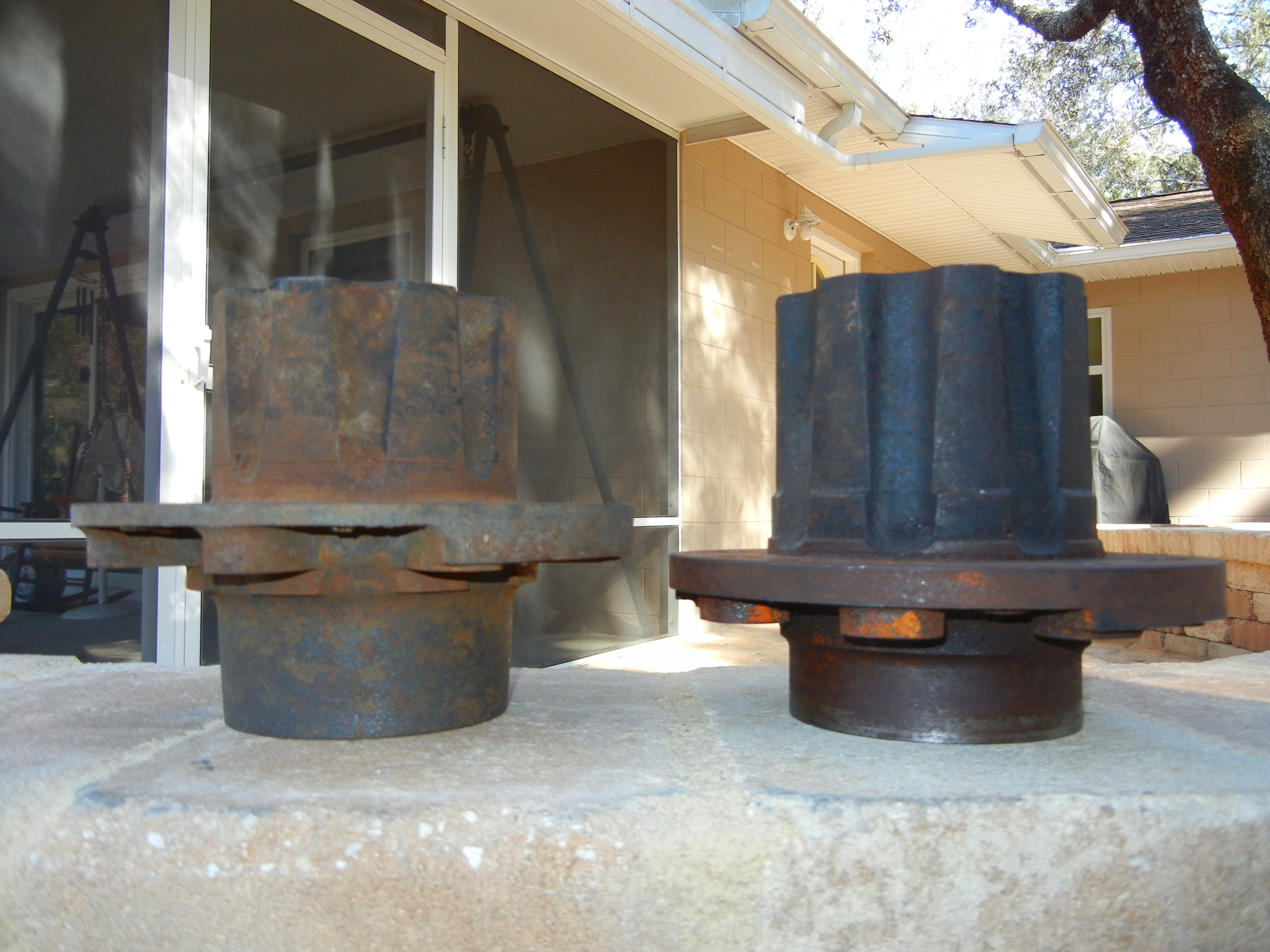
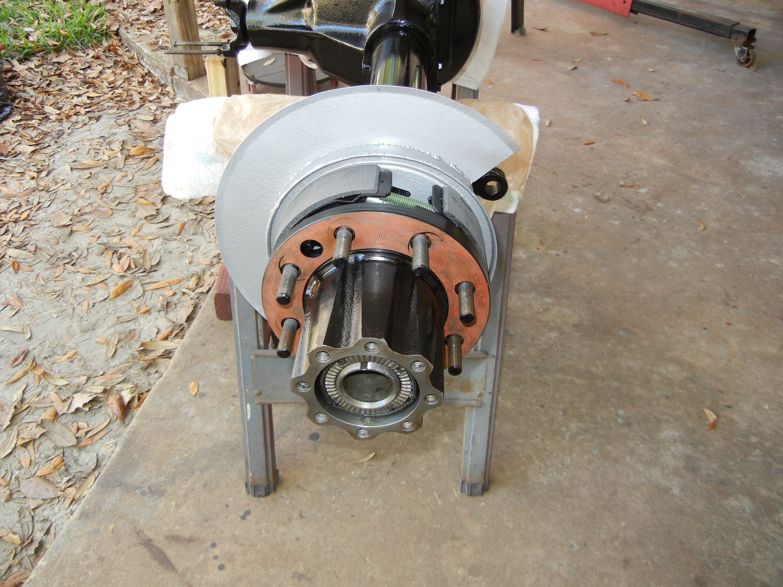
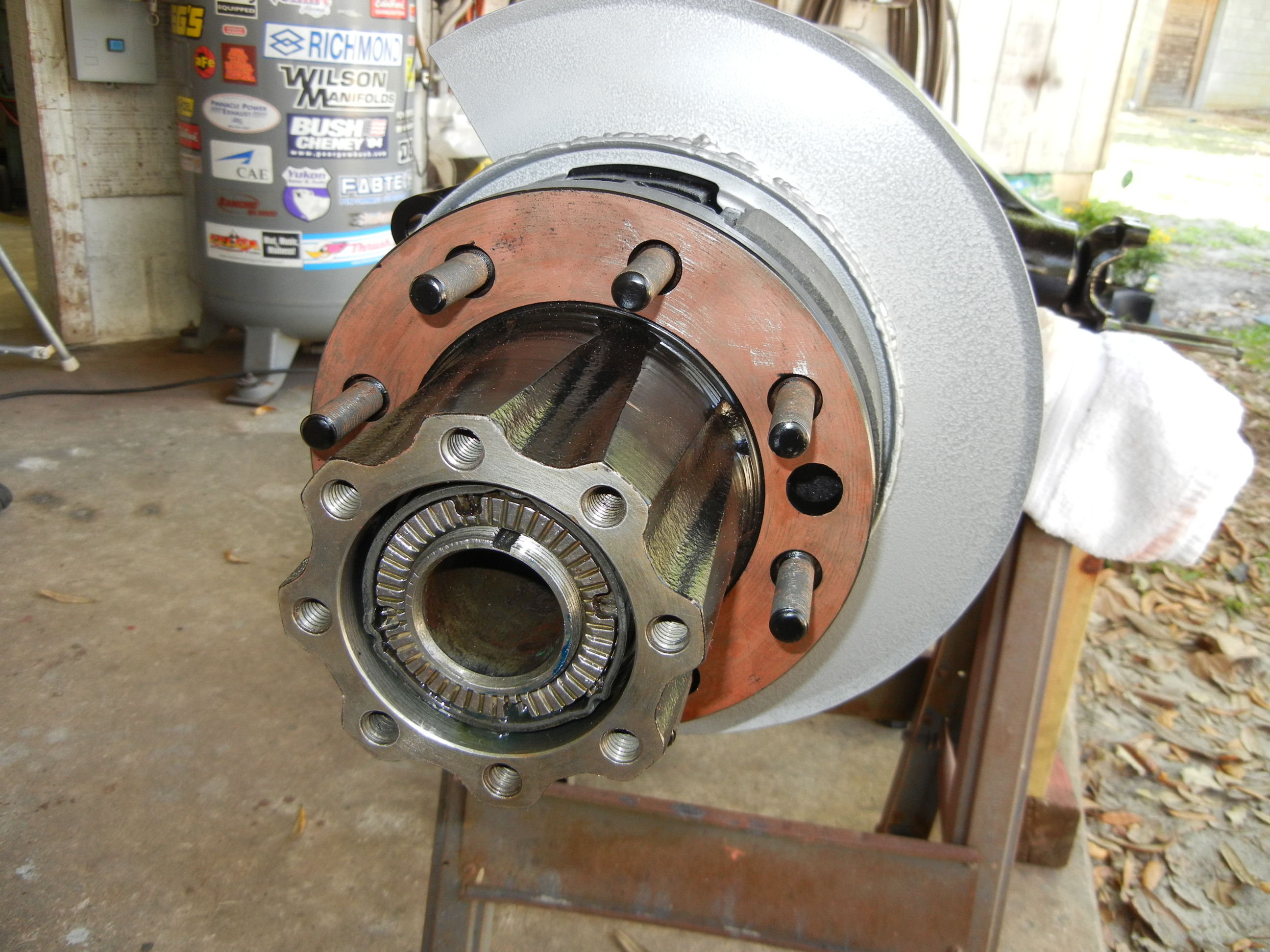
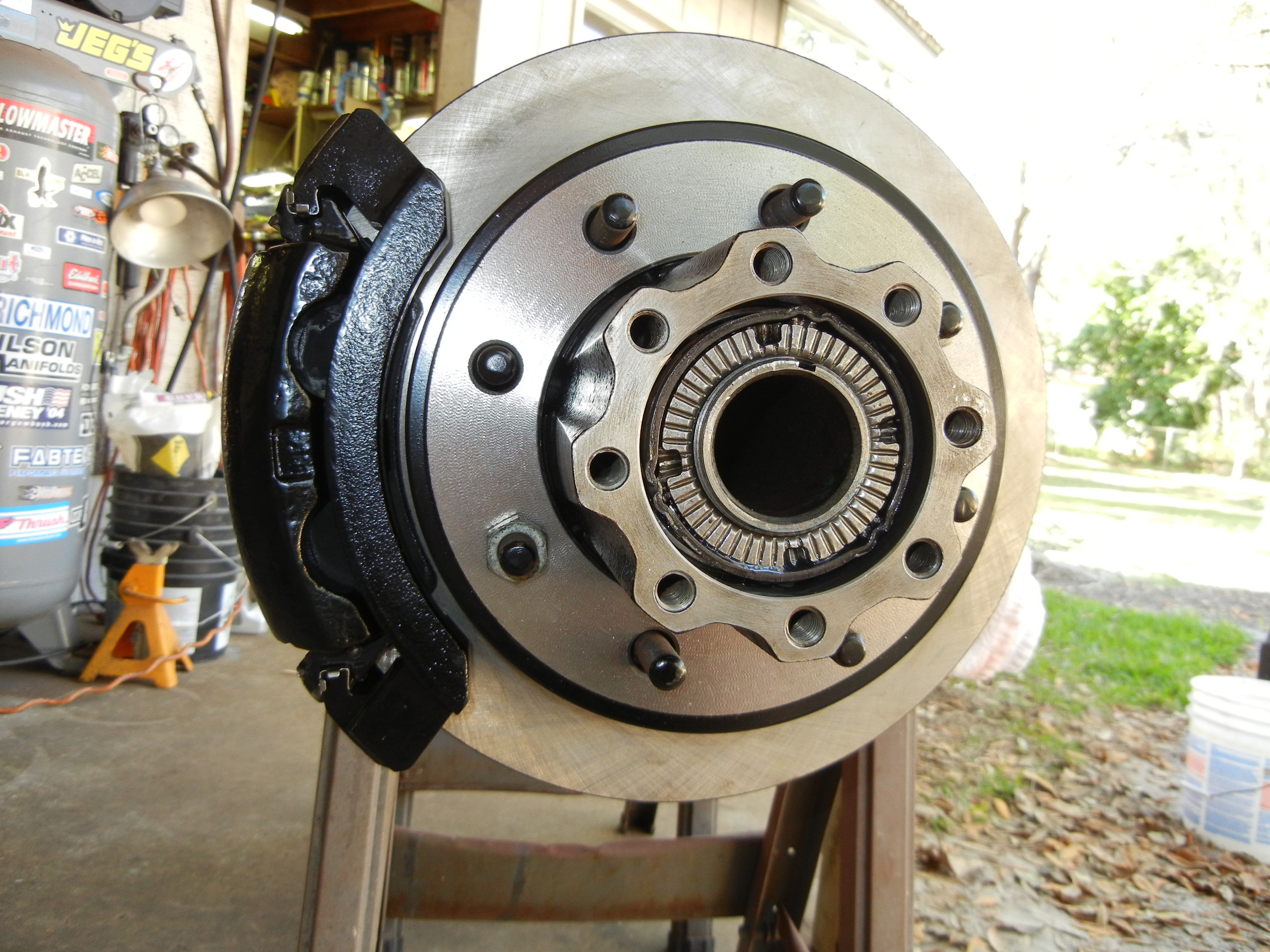
After six long years, we wondered why we saved the original van Dana 60
hubs. For whatever reason I sure am glad we did as I will be using them over
the originals. Unlike the Sterling, this axle mounts the drum to the
backside of the hub. Newer designs have the drum or rotor mounted on the
outside of the hub for quicker and easier servicing. Since I plan to
replicate the newer design, it was a no brainer not to reuse the 60 hubs.
Plus this already had the hub centric ring for centering the rotor and the
proper inner bearing hub diameter (remember the Sterling was so large we had to
cut the park brake shoes down?). The only issue right now are the wheel
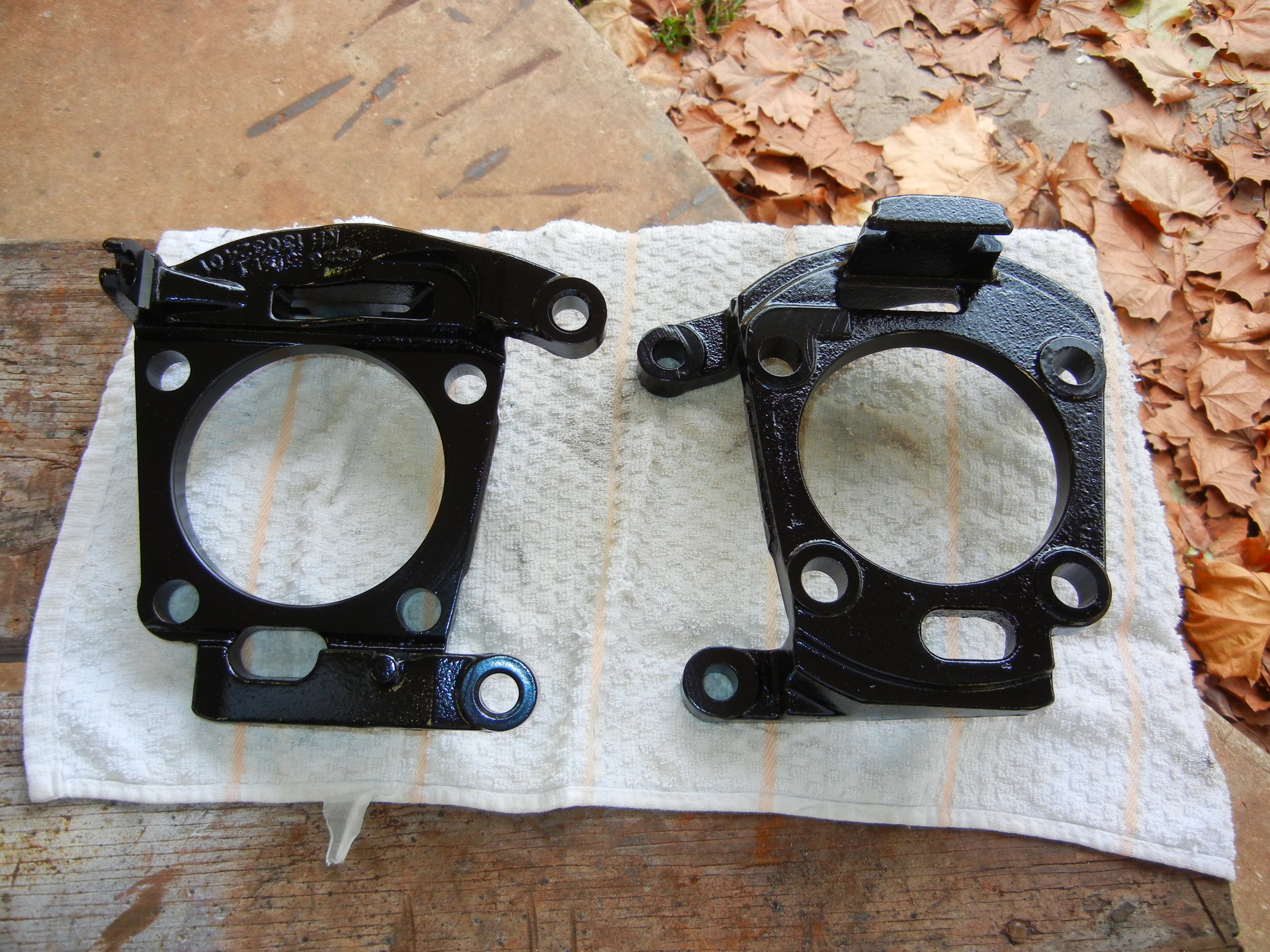
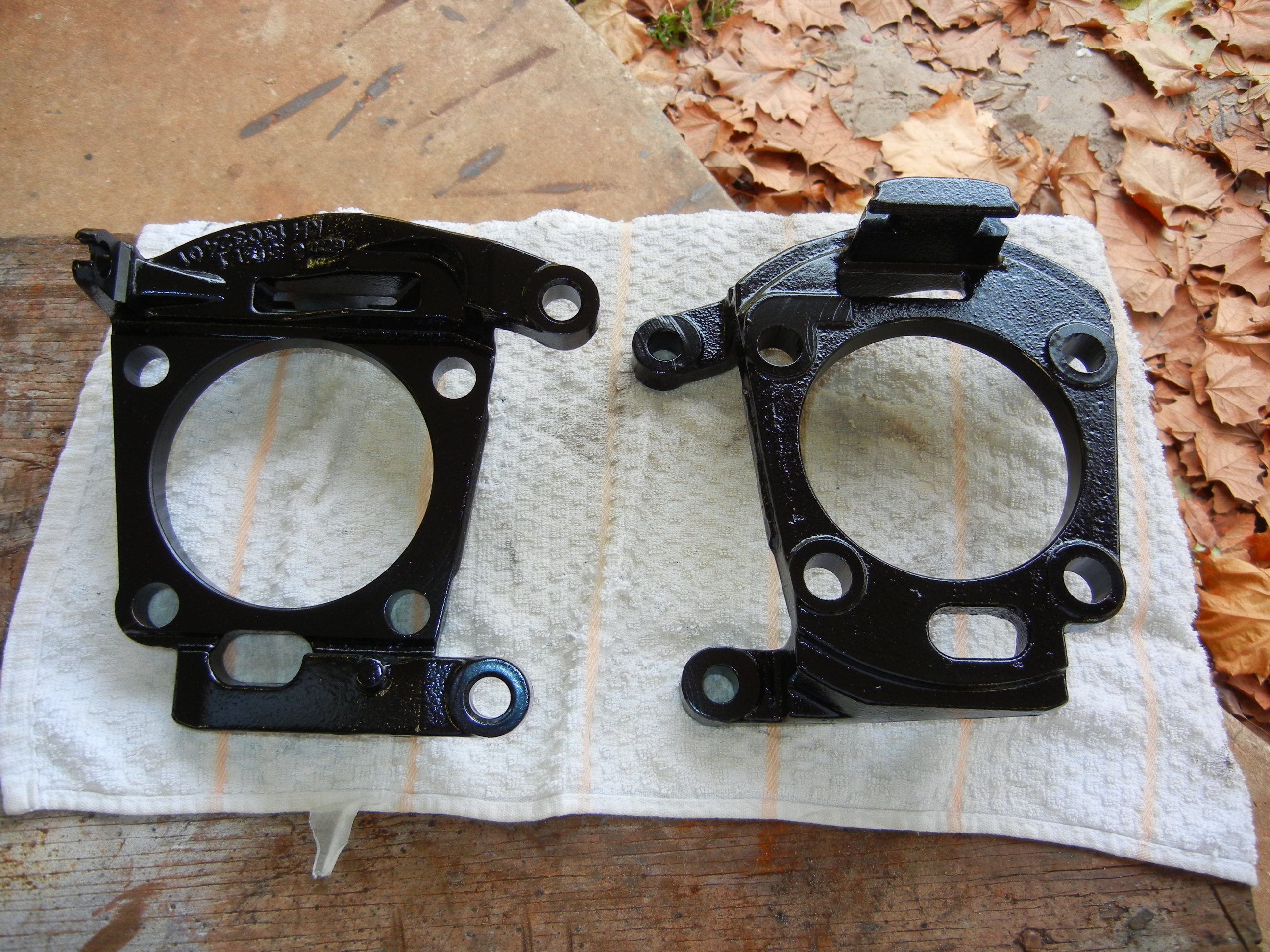
studs which we did not save (more on this later). In the photos below, D70
hub on left and van D60 hub on right.
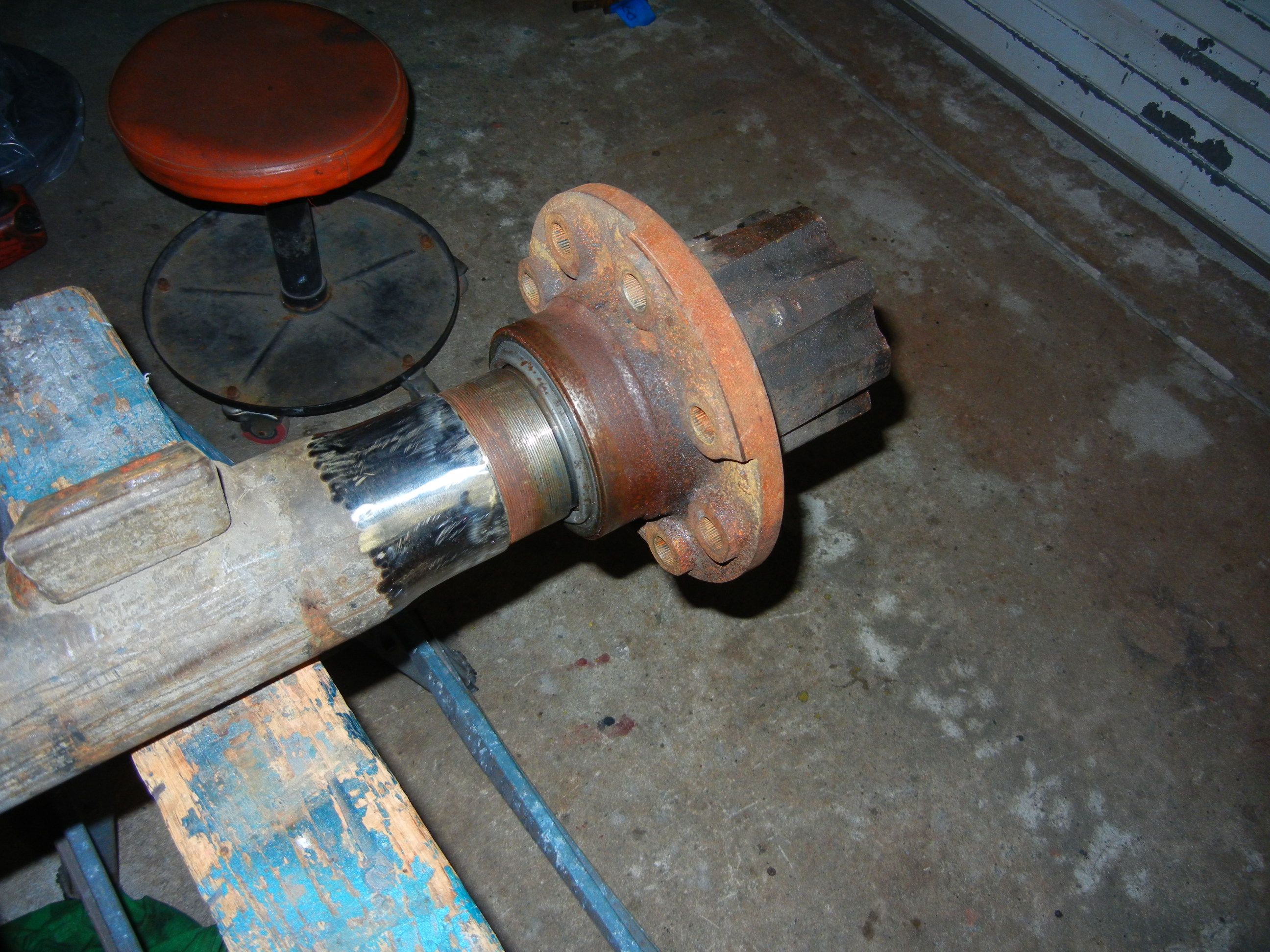
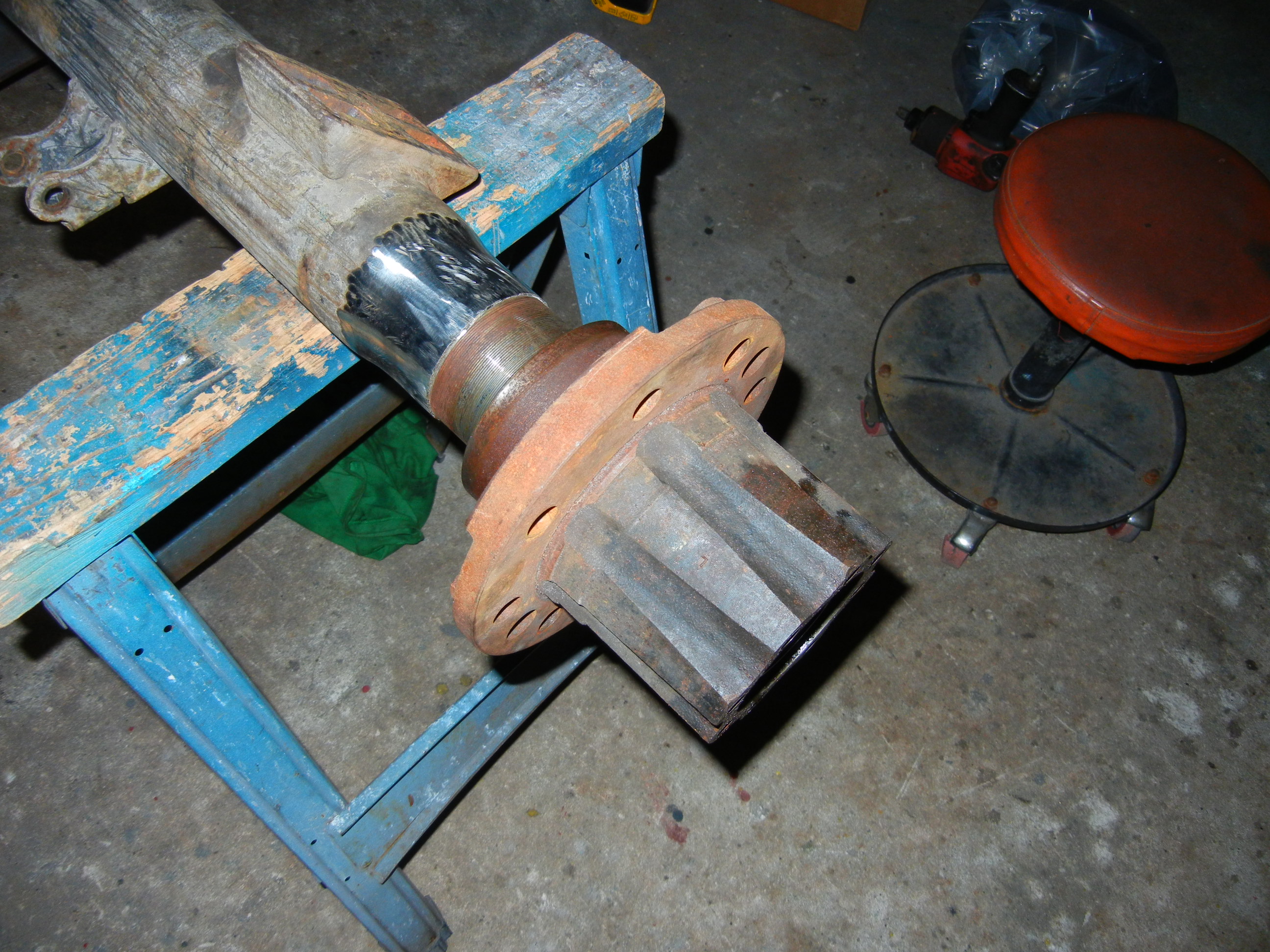
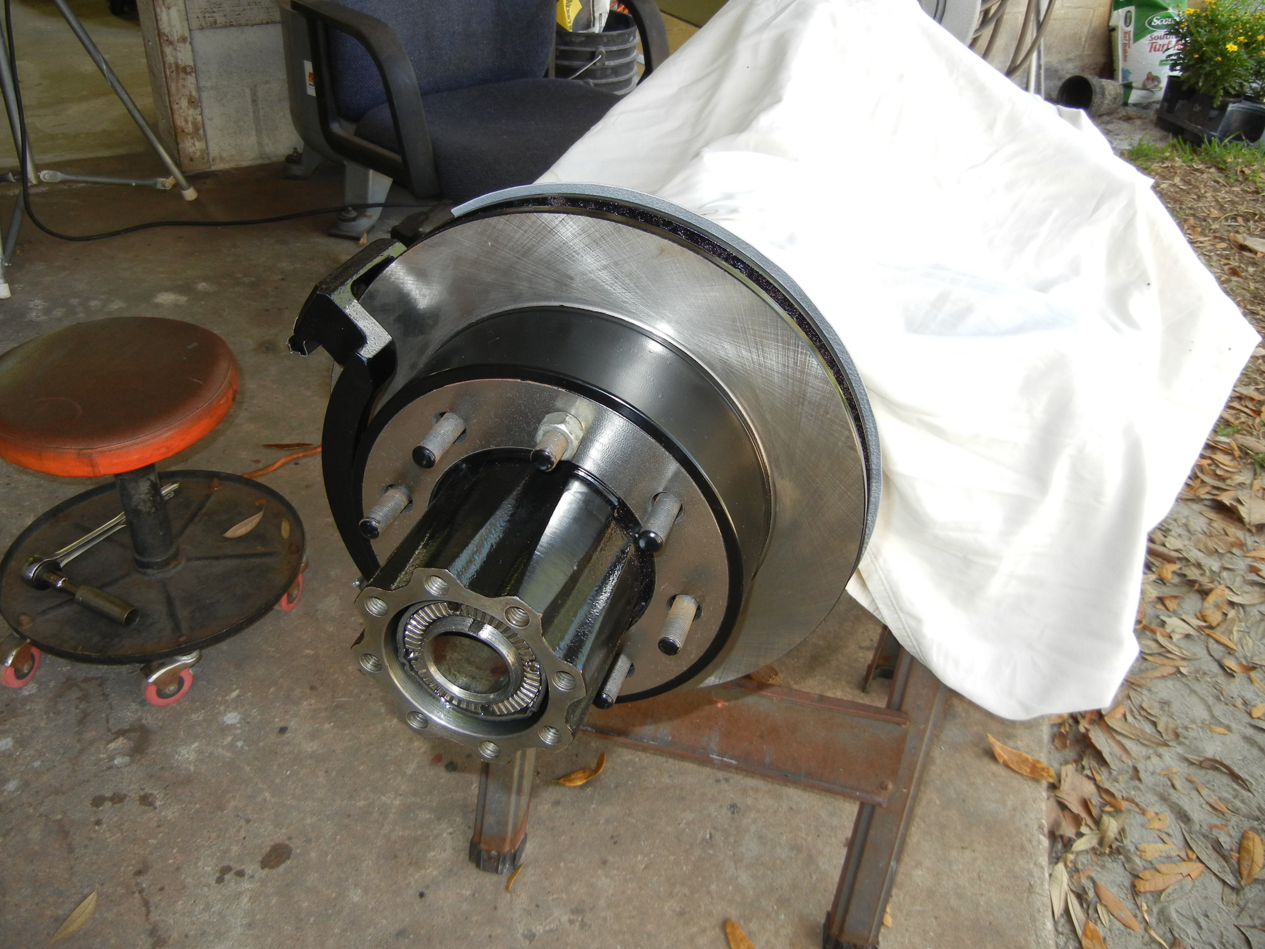
Test fitting the D60 hub on D70 proves it will work as the bearings are the
same size and correct spacing. We even bolted in the axles just to be sure.
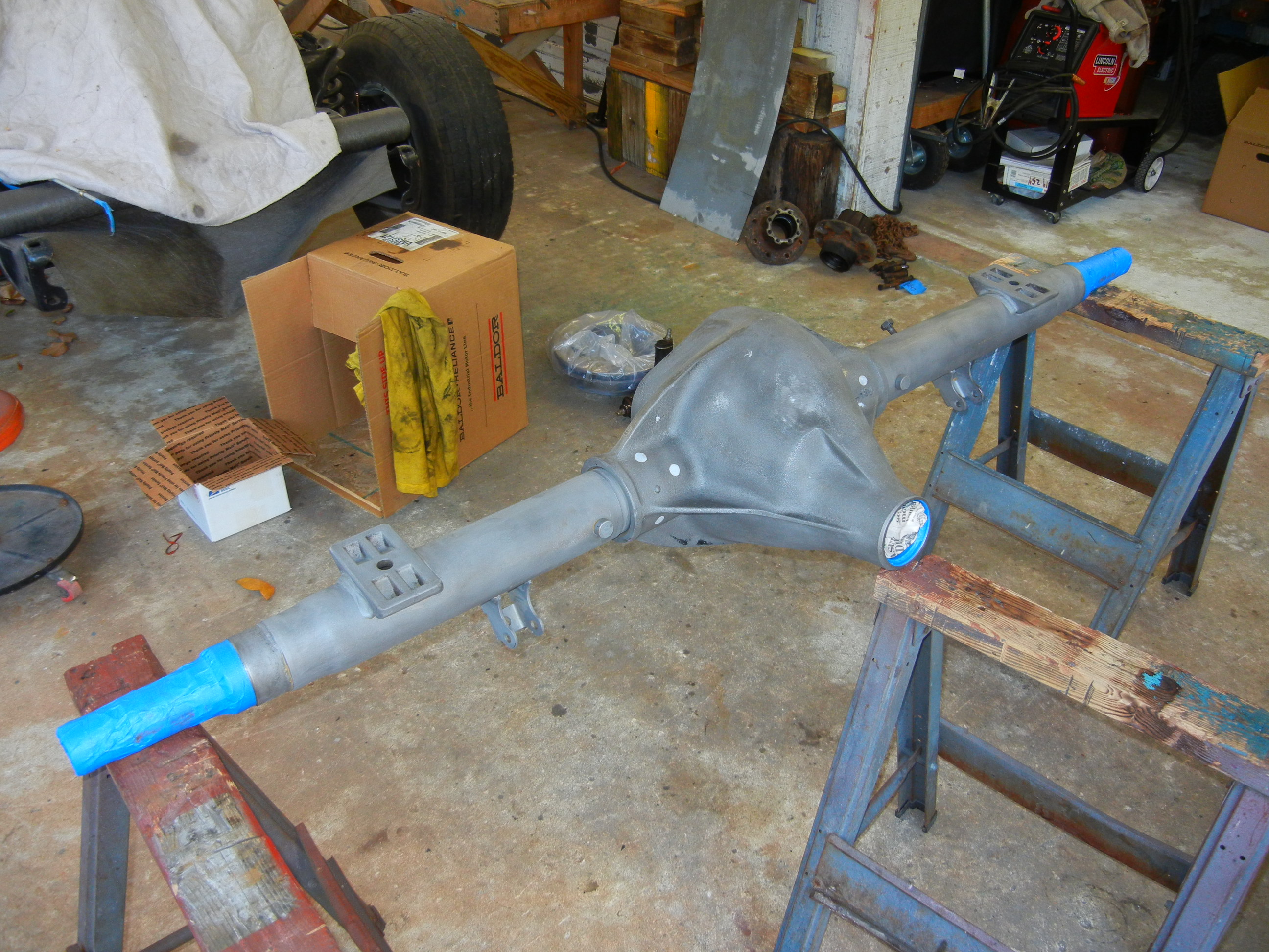
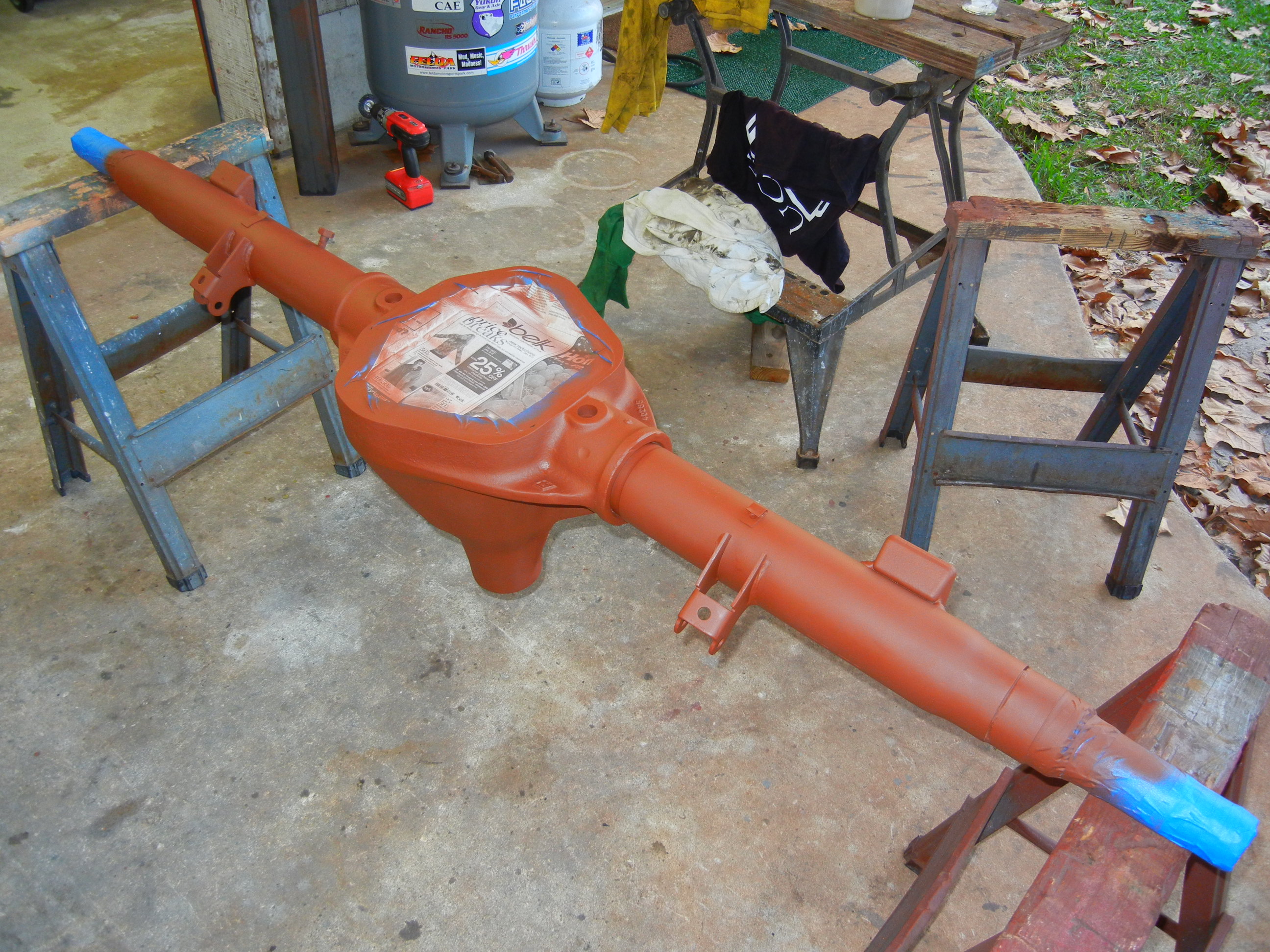
Now came time to sandblast and degrease the axle. No pics were taken due to
obvious reasons. Afterwards the plug weld holes were filled in with "Quick
Steel". Overkill...quite possibly. If it bothers you, go build your own
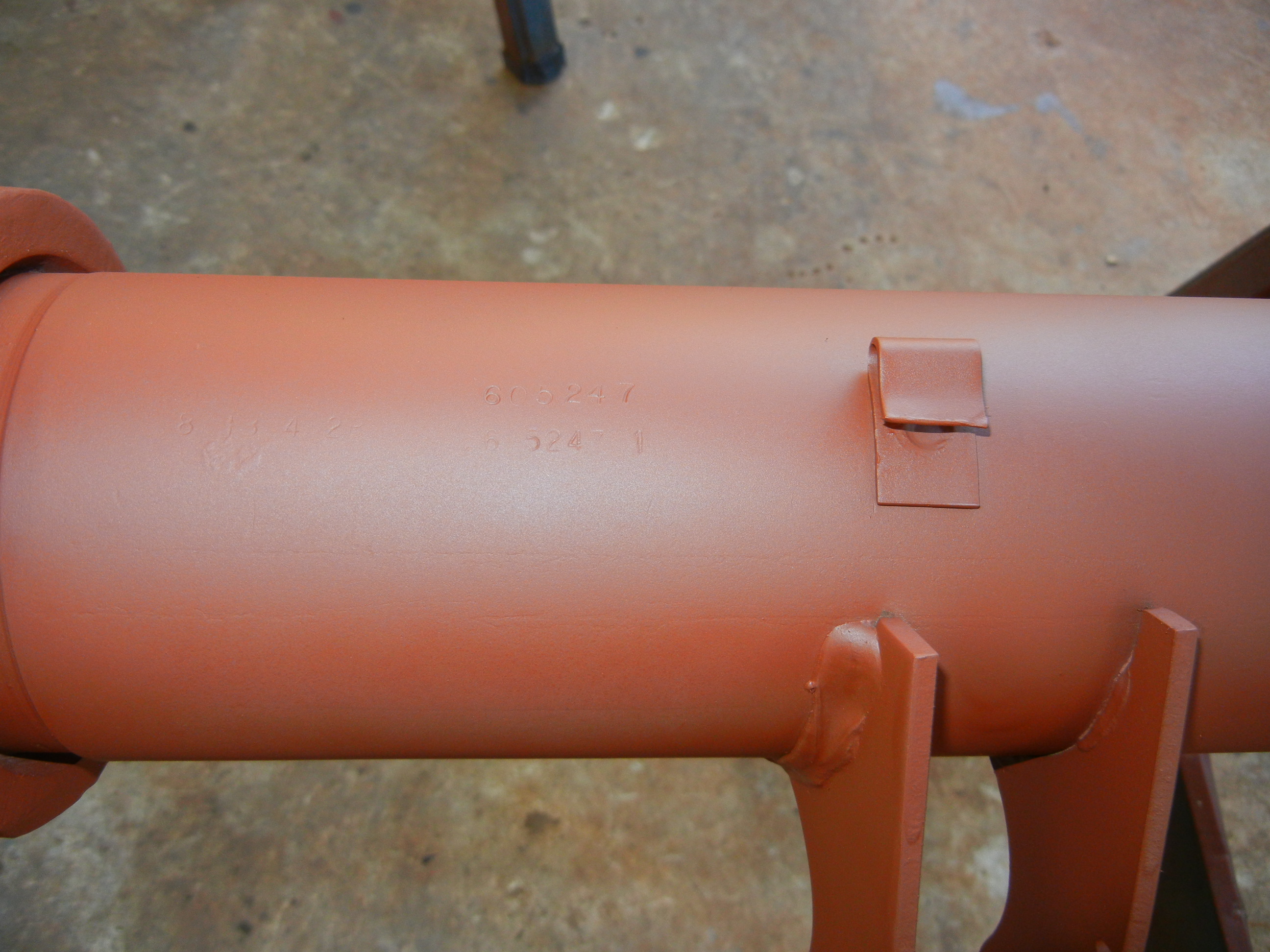
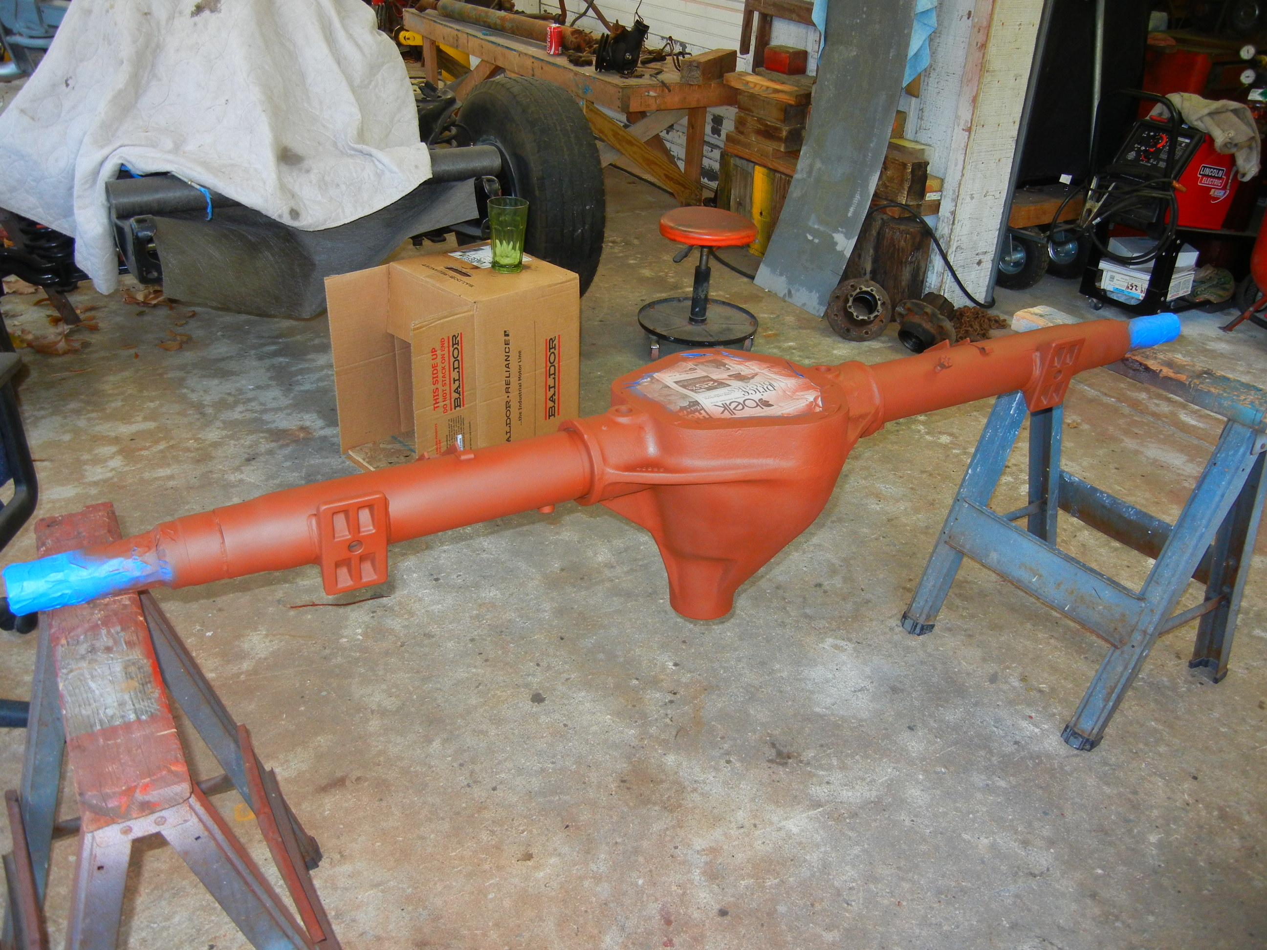
website! More red primer and restamping of the original BOM minus the ratio
digit as this is no longer 3.54:1.
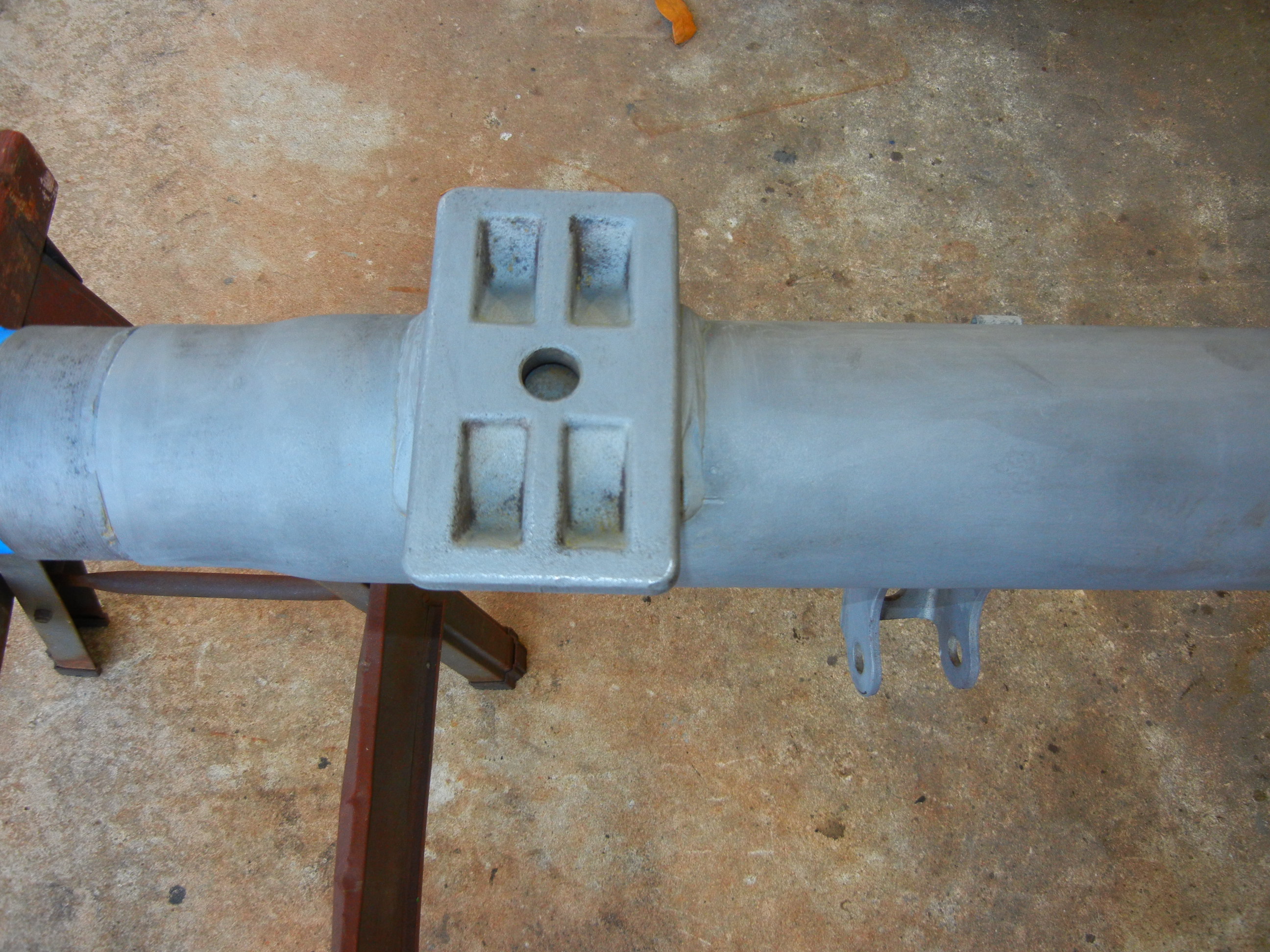
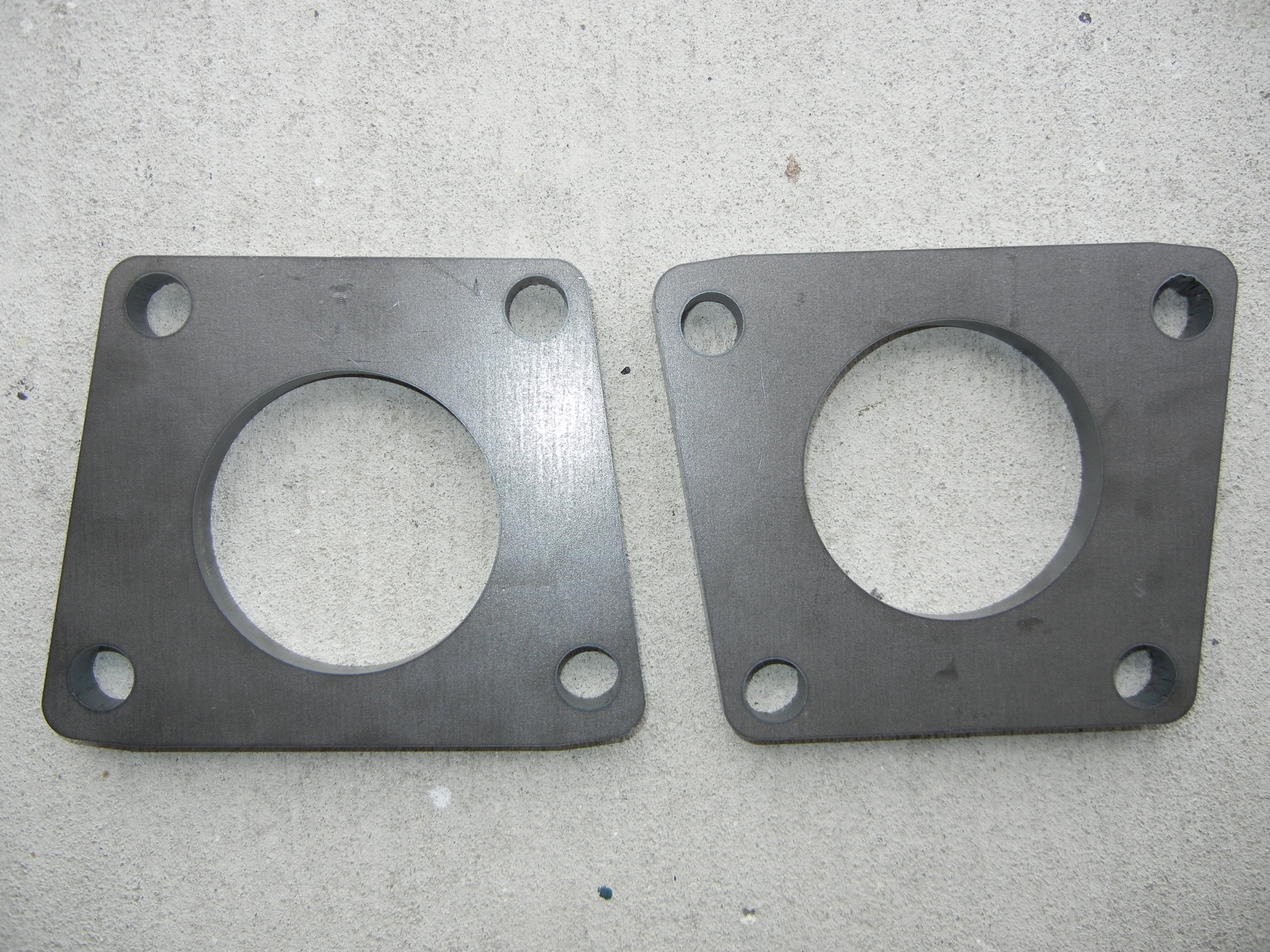
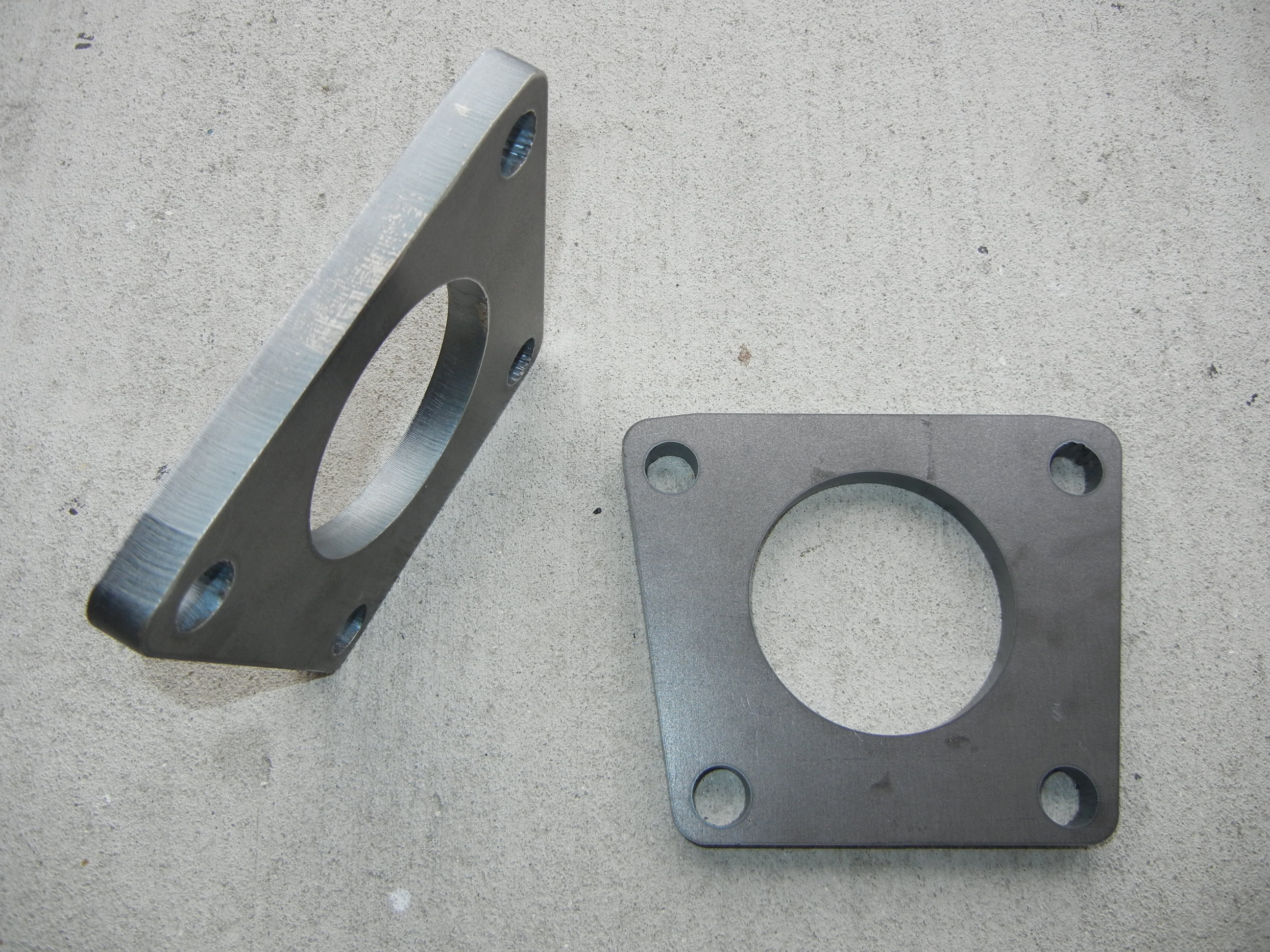
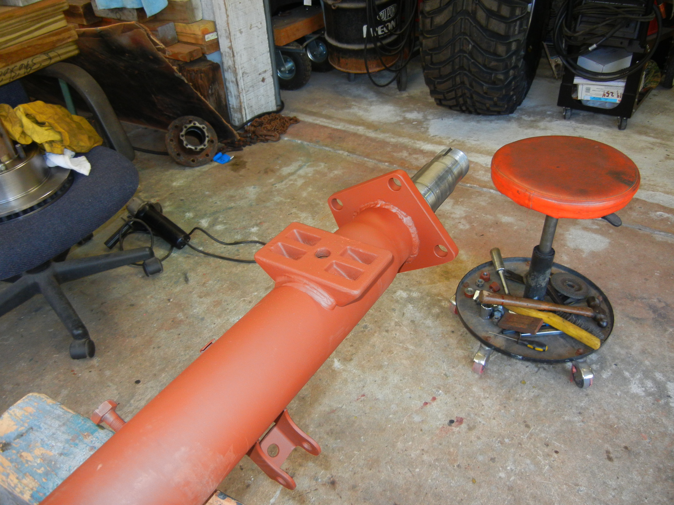
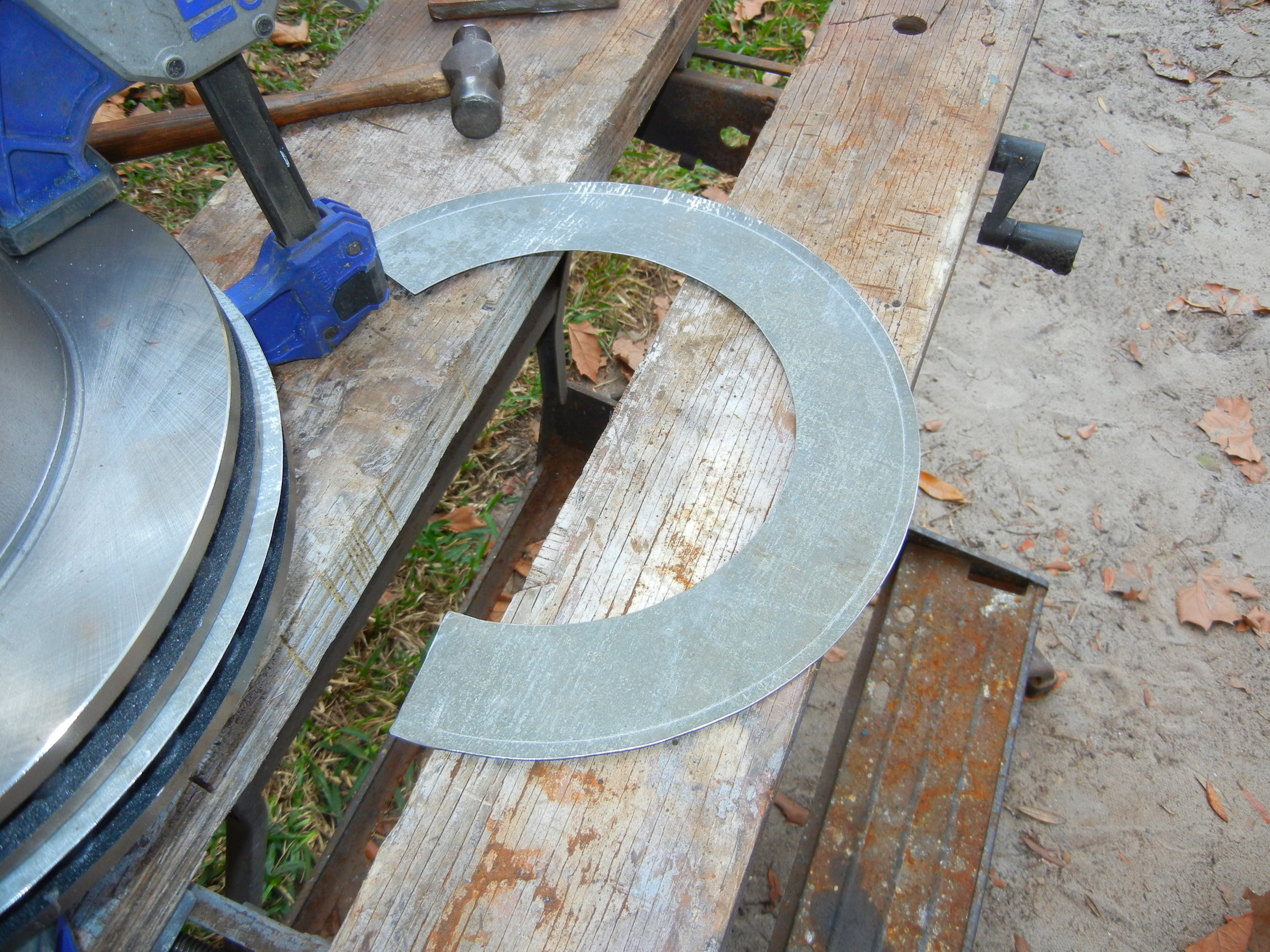
Here are the new laser cut tube flanges from my CAD sheet above. The shop
that made mine gave me a great price on the pair being made on their laser
machine. Other shops quoted me higher prices using water jet machines. I do
not know the pros and cons of laser cutting over water jetting. I think it
just depends on the material thickness and machine's capabilities. Again
much time and dedication went into the measuring and creation of the CAD
file above. If you use this on your project please let me know how it worked
out for you. I am always open to a pat on the back!
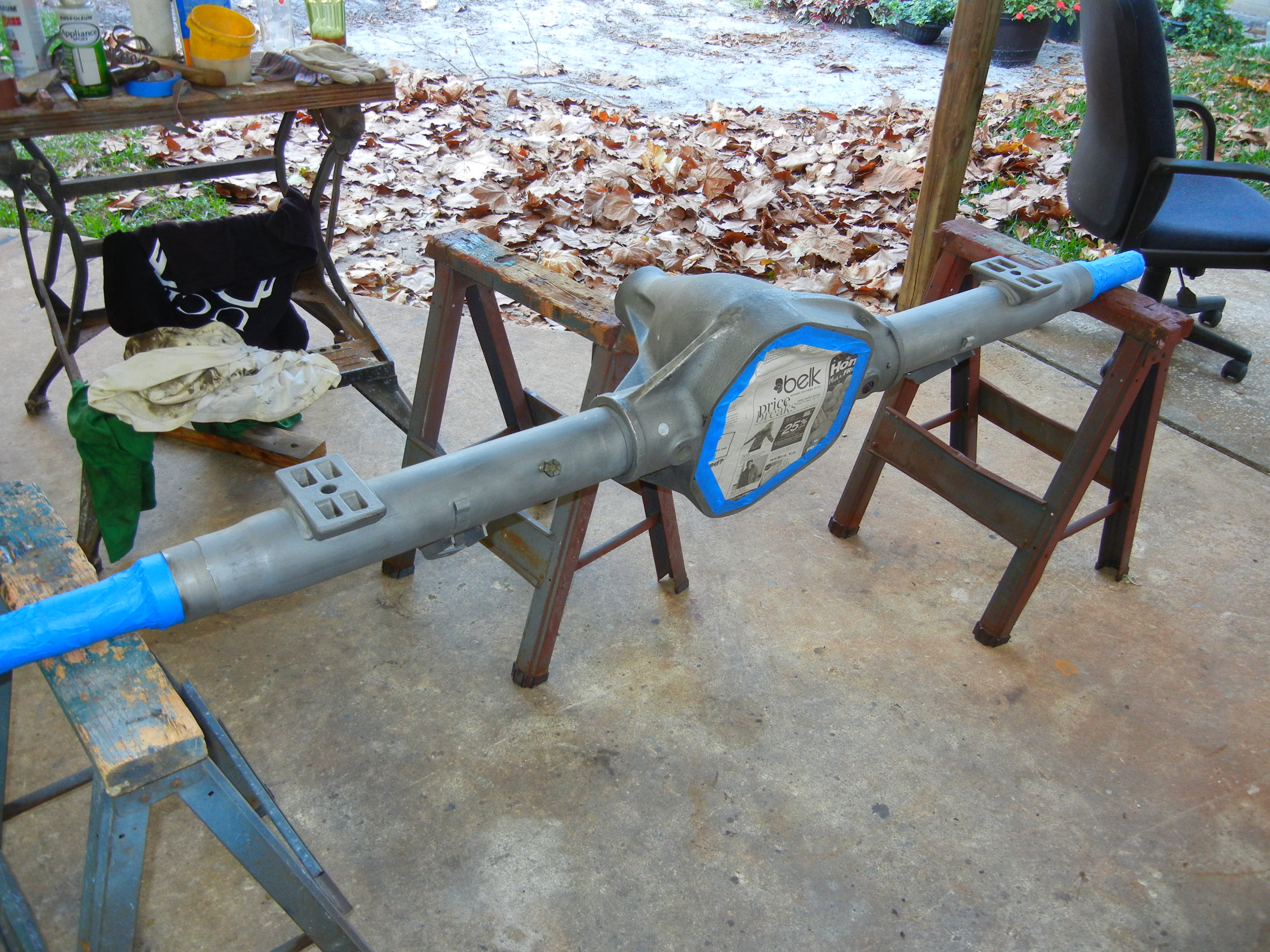
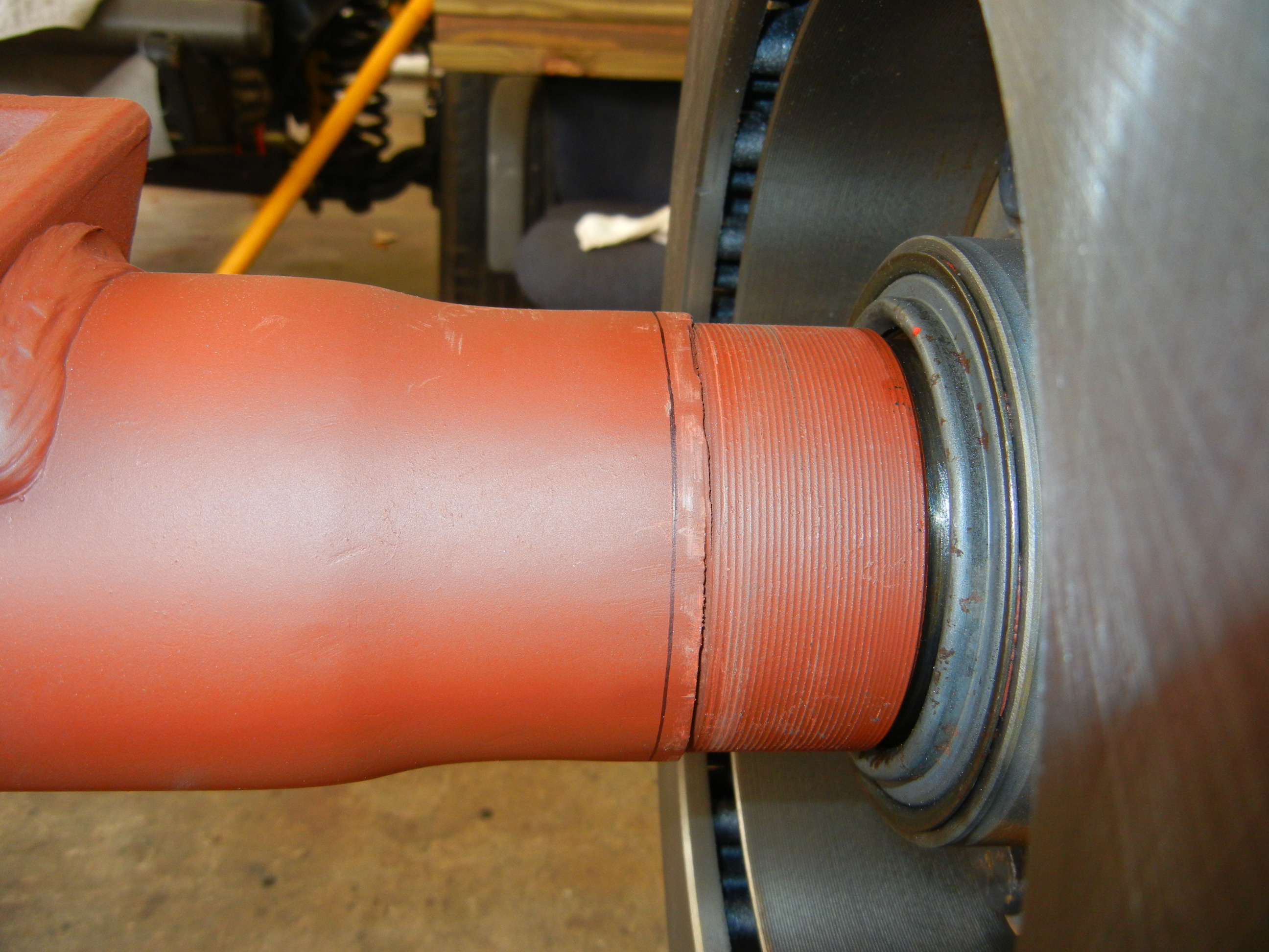
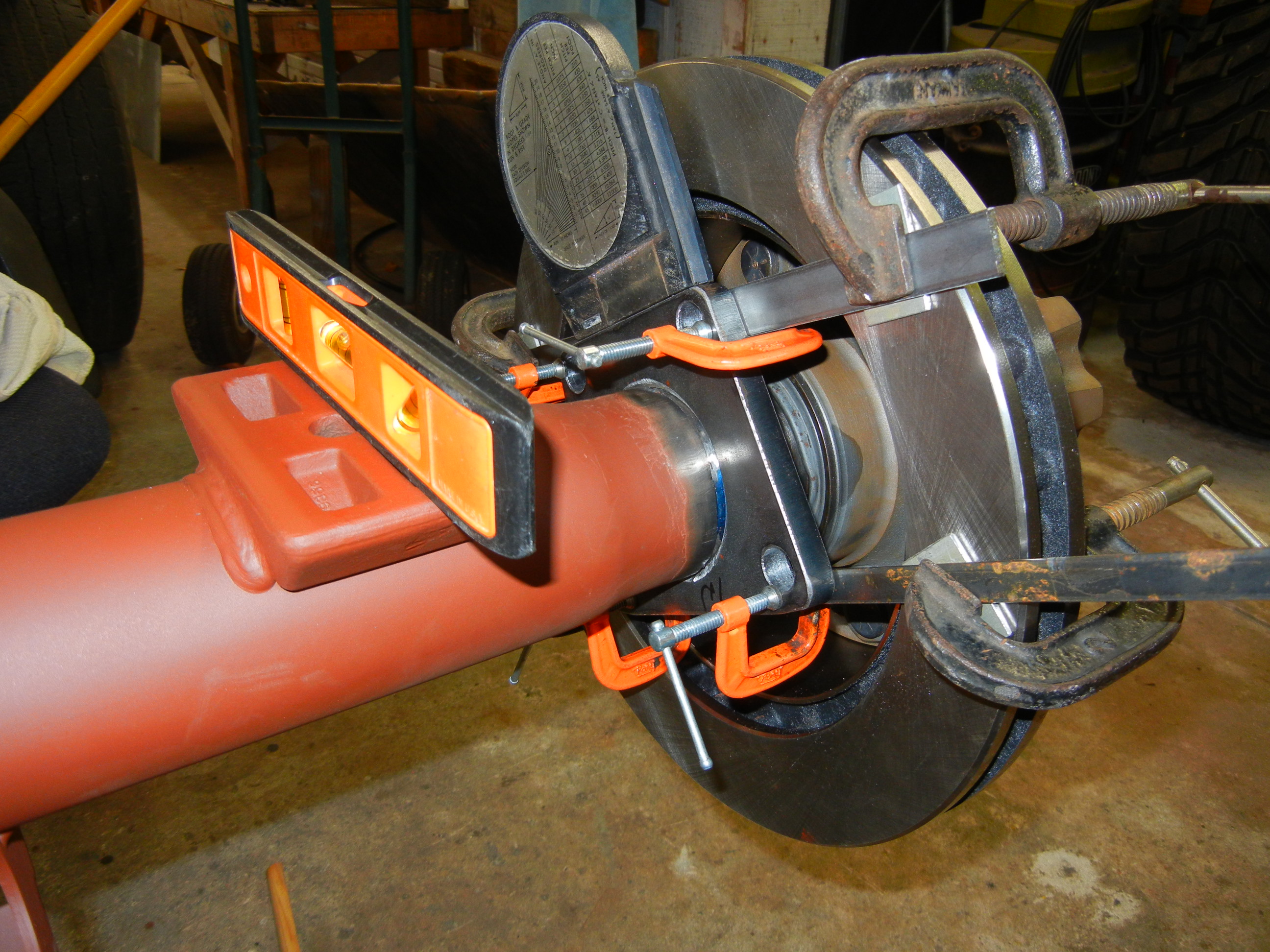
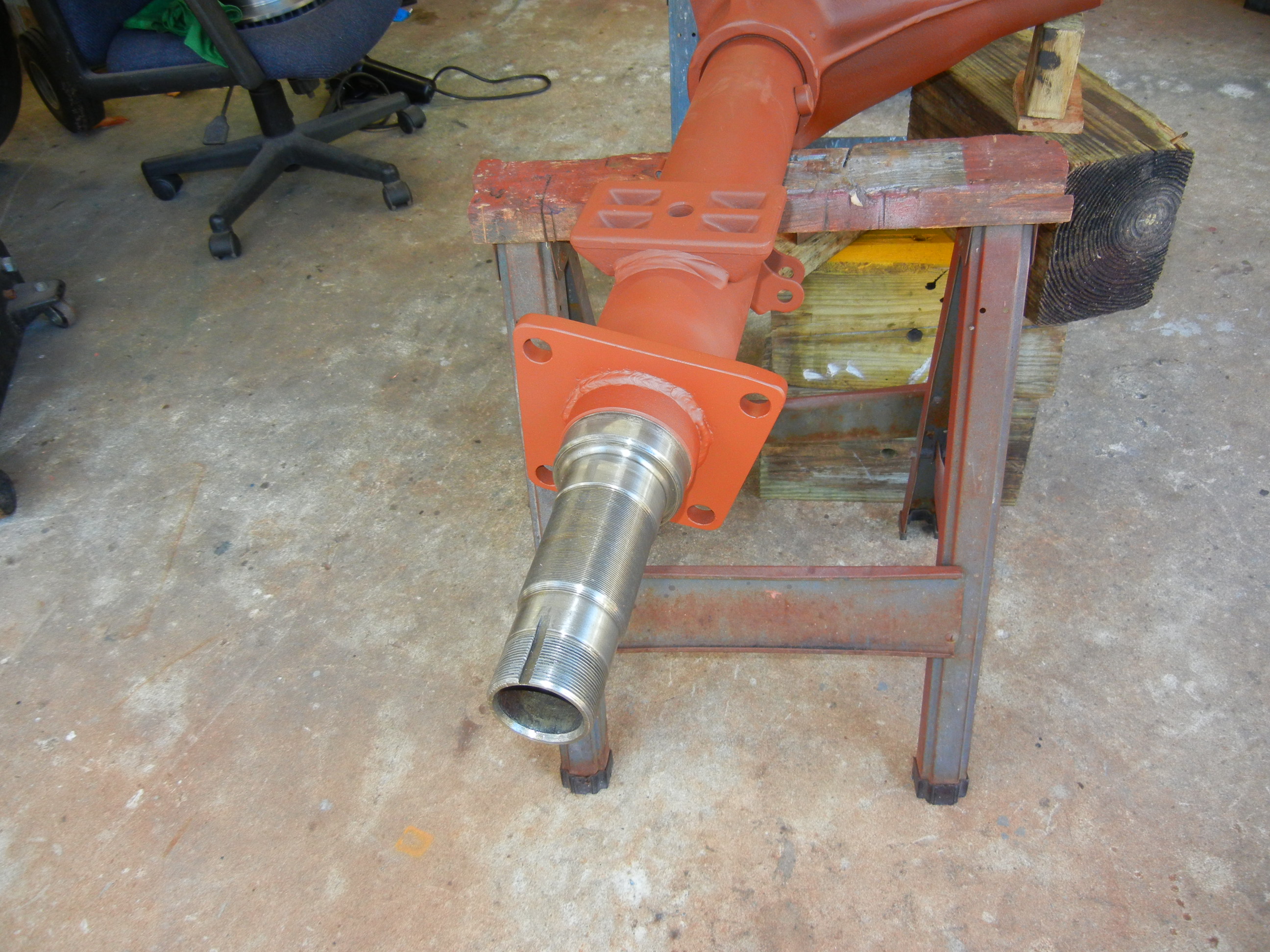
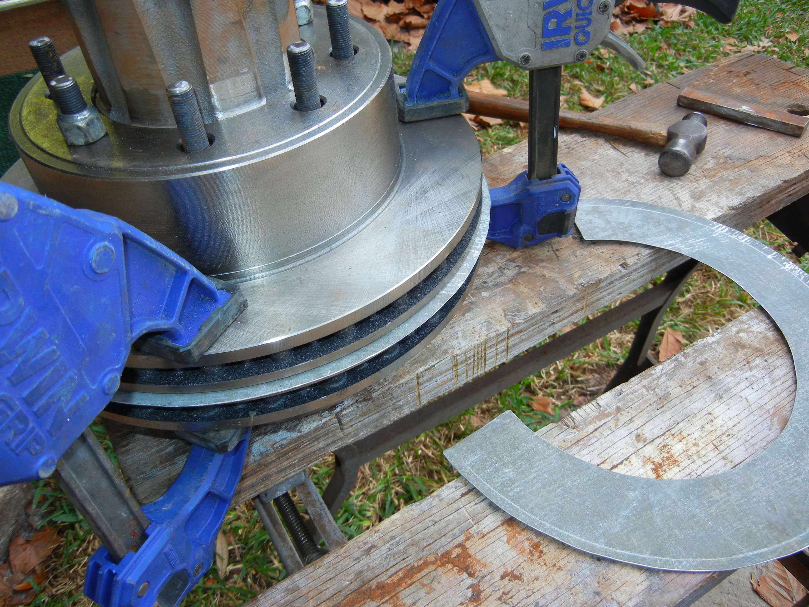
The flange will now be bolted to the backing plate and slid over the axle
tube with the caliper and rotor attached to determine exactly where the
flange will be welded. This is how we did it on the Sterling axle by means
of a parallel clamping method which is needed to ensure the pads are
perfectly aligned over the rotor.
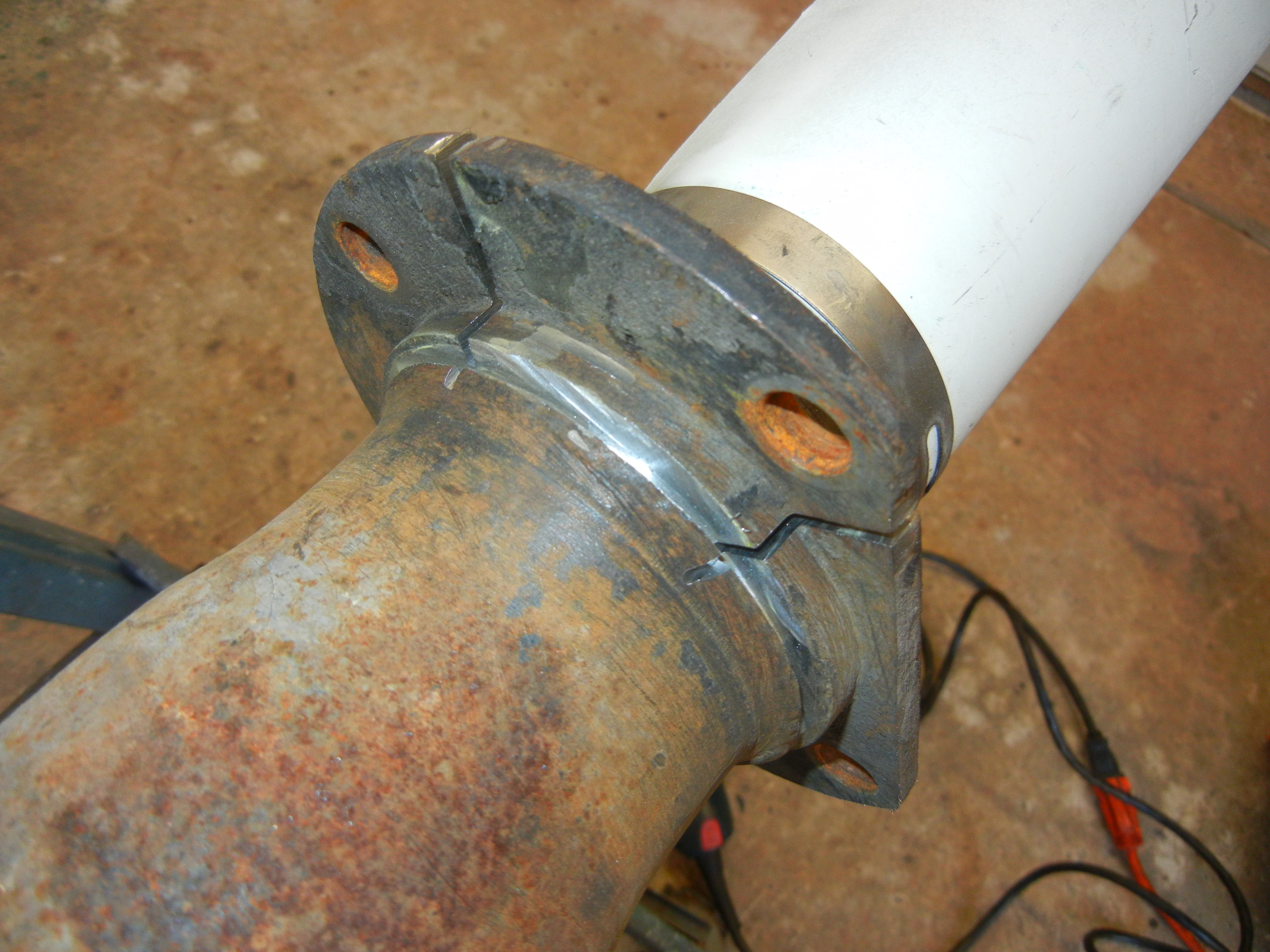
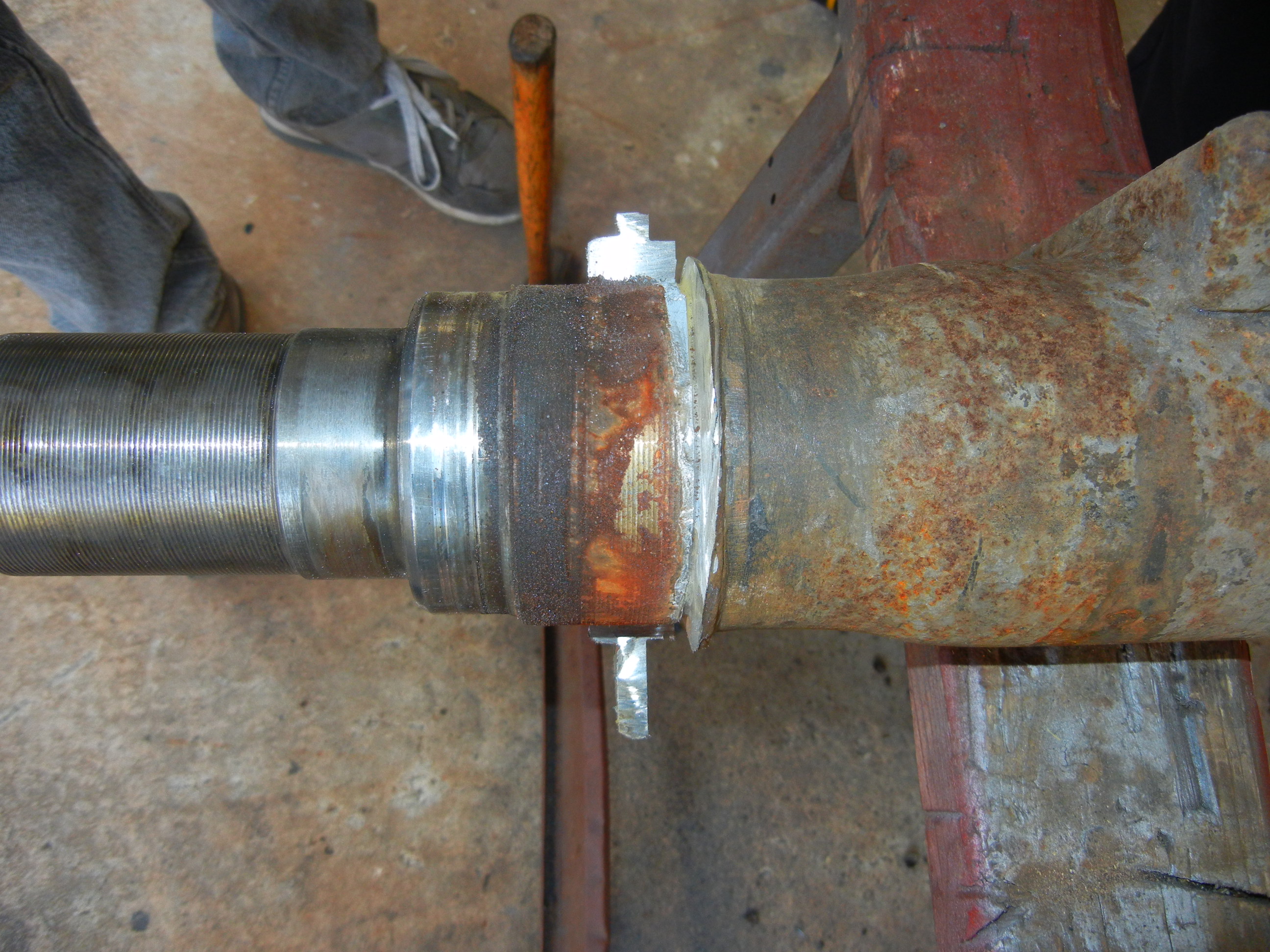
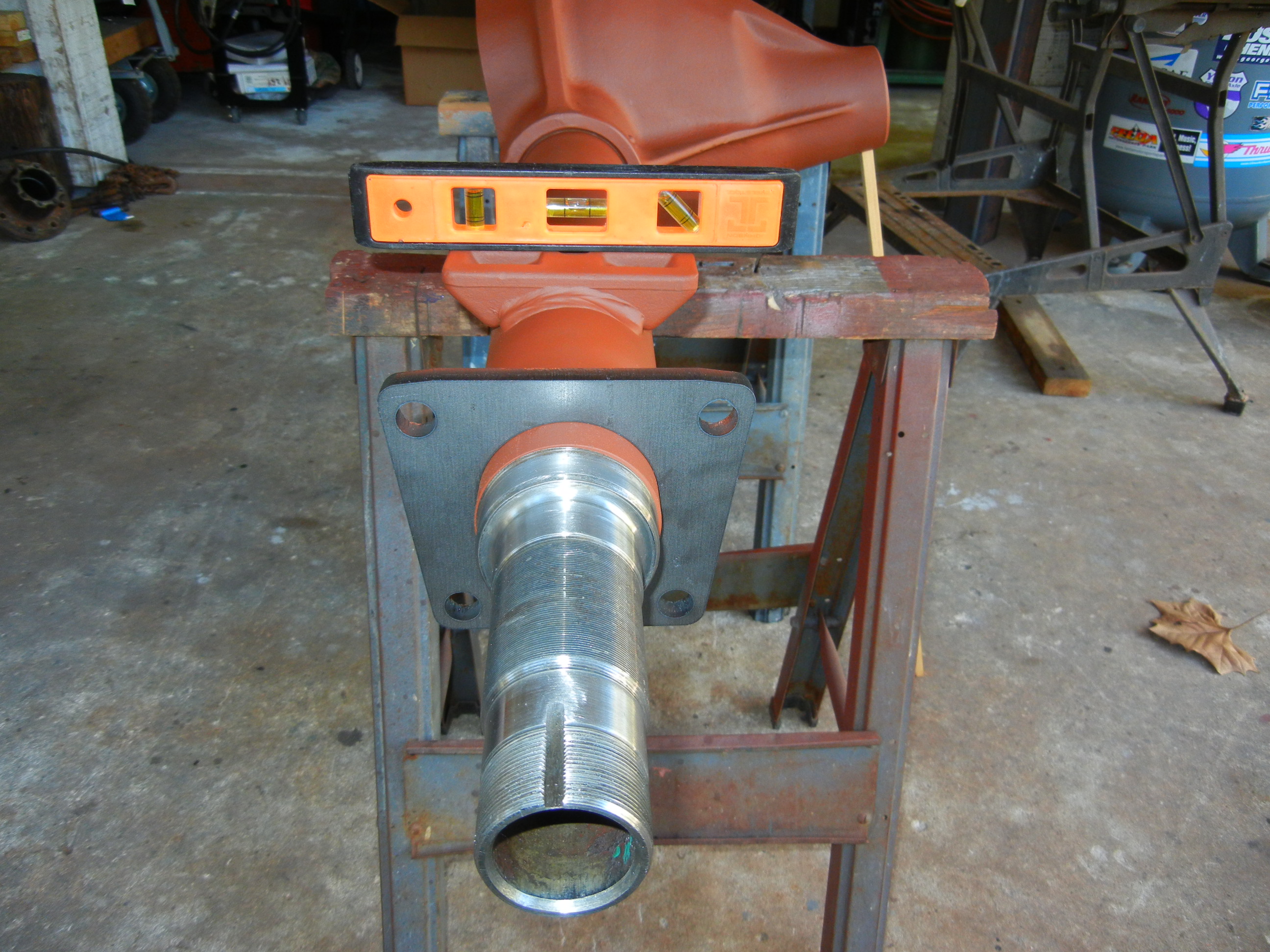
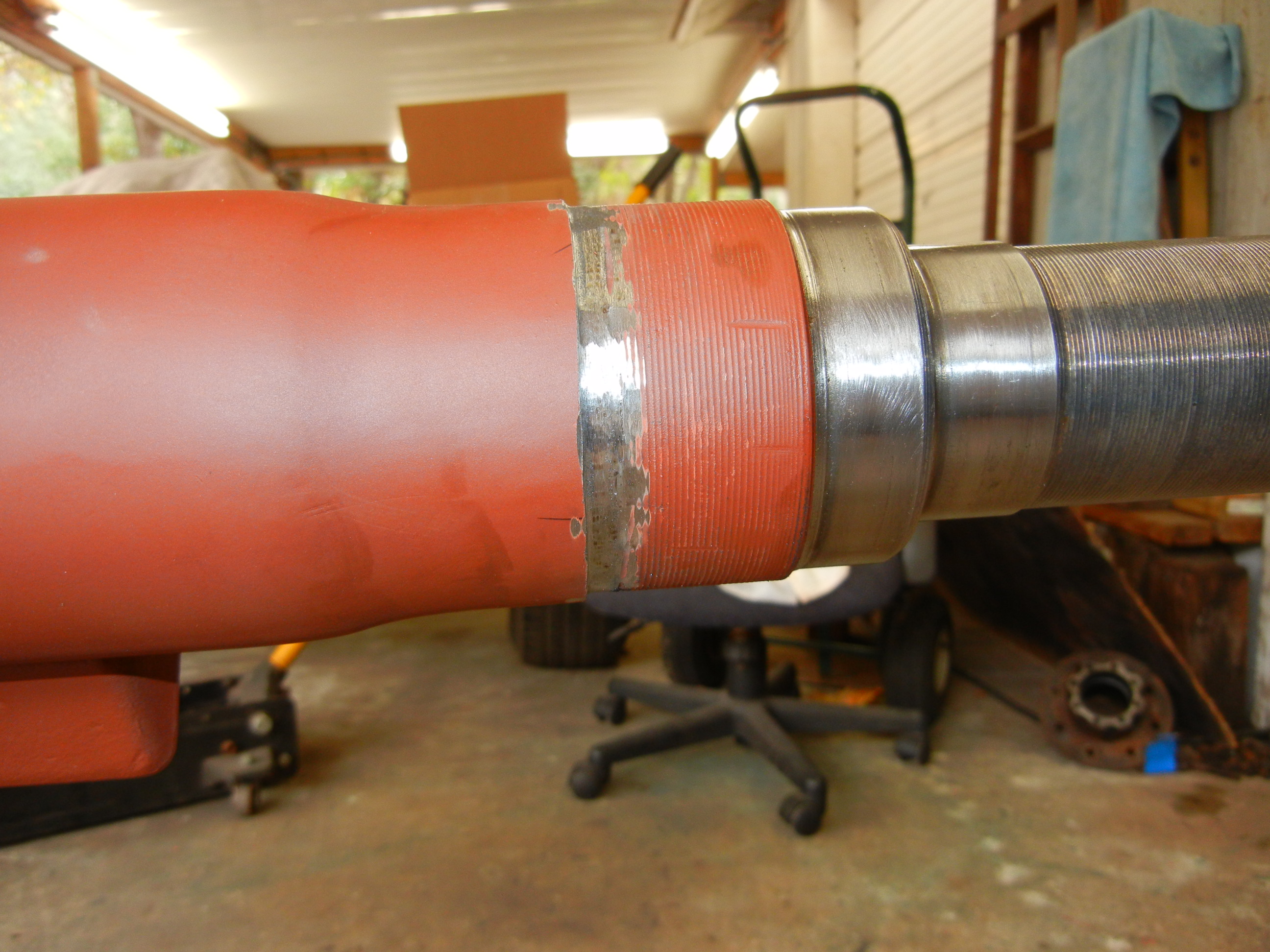
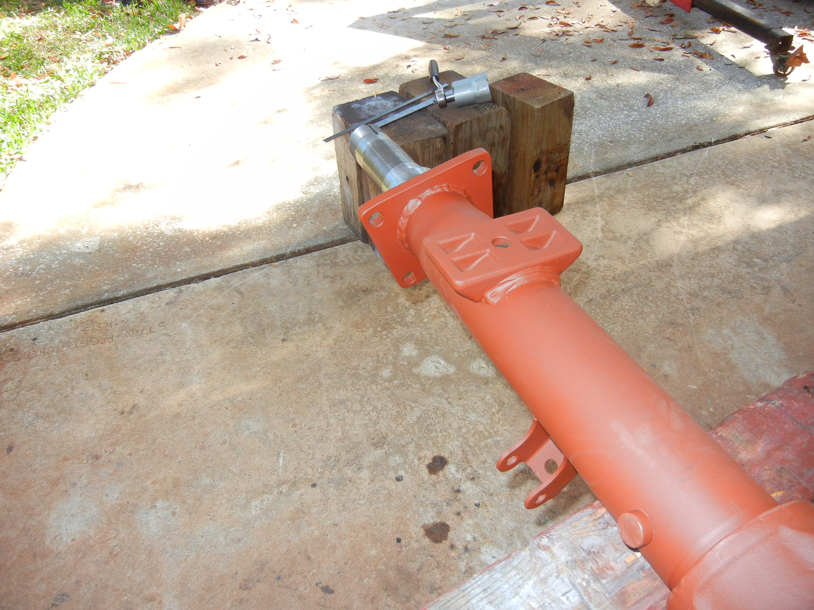
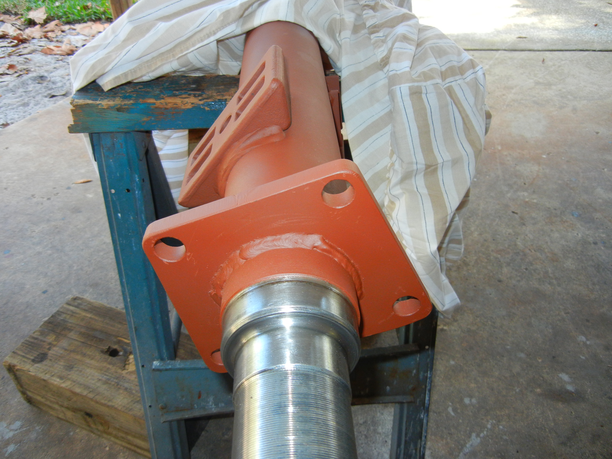
Welding on the new flange took some finesse to make sure it
was oriented properly and at the correct back spacing. We chamfered the
edges of the flanges so more weld penetration would result. A little more
grinding was needed on the tube where the original flange resided so the new flange
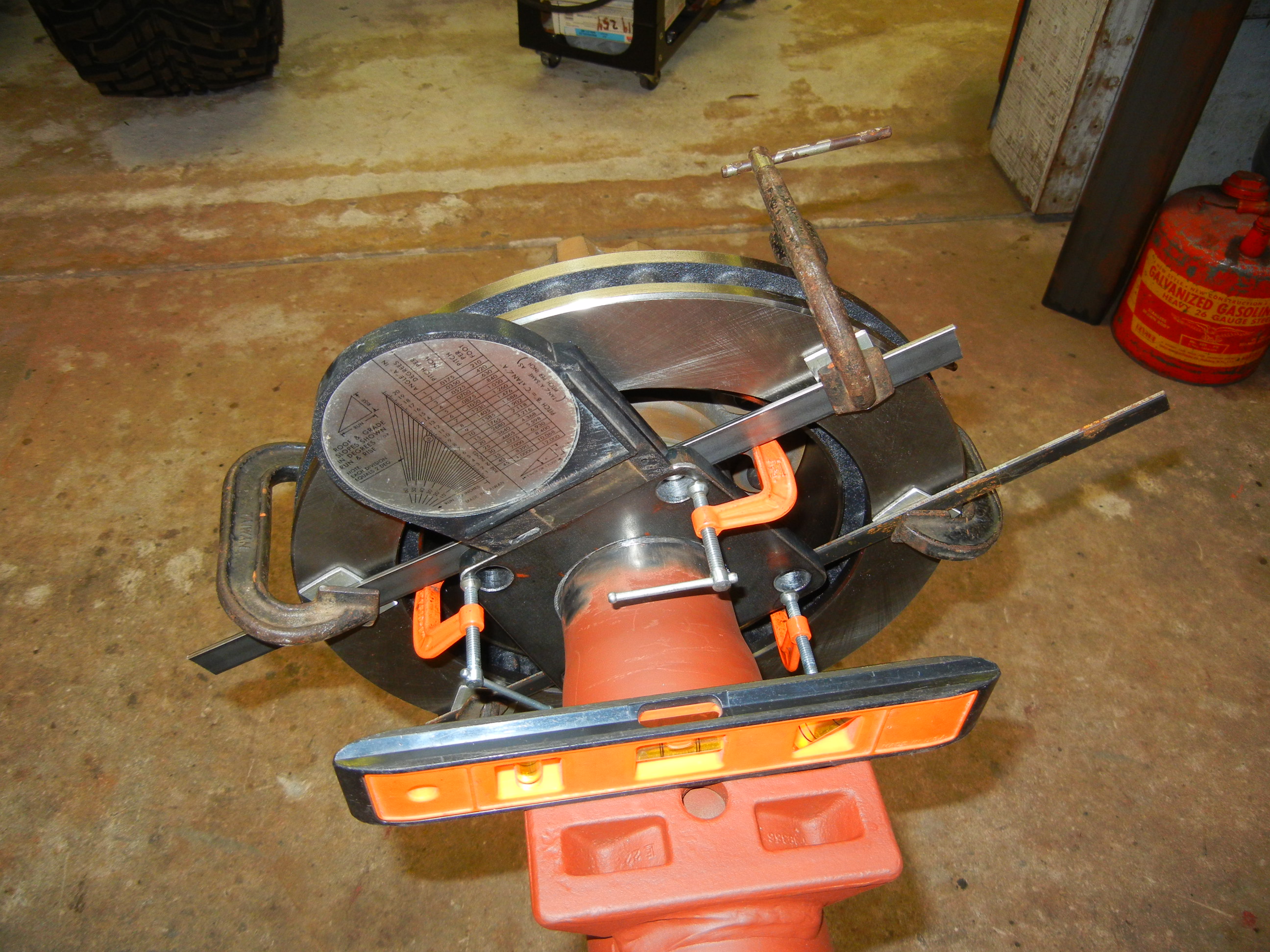
would be located in the correct location. The method for alignment was
simple, set the perches level and then rotate the flange until it matched
the angle of the D60 axle.
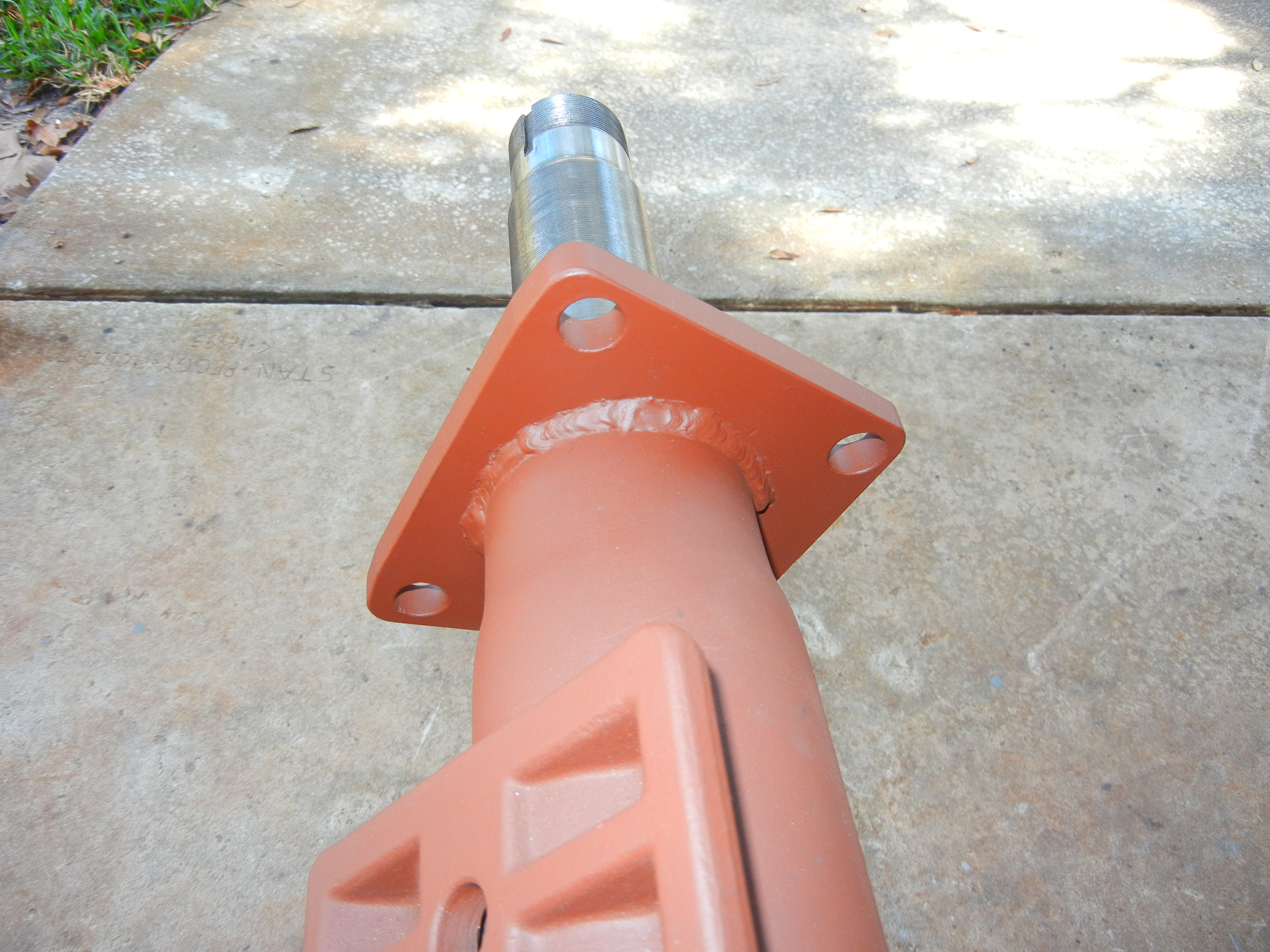
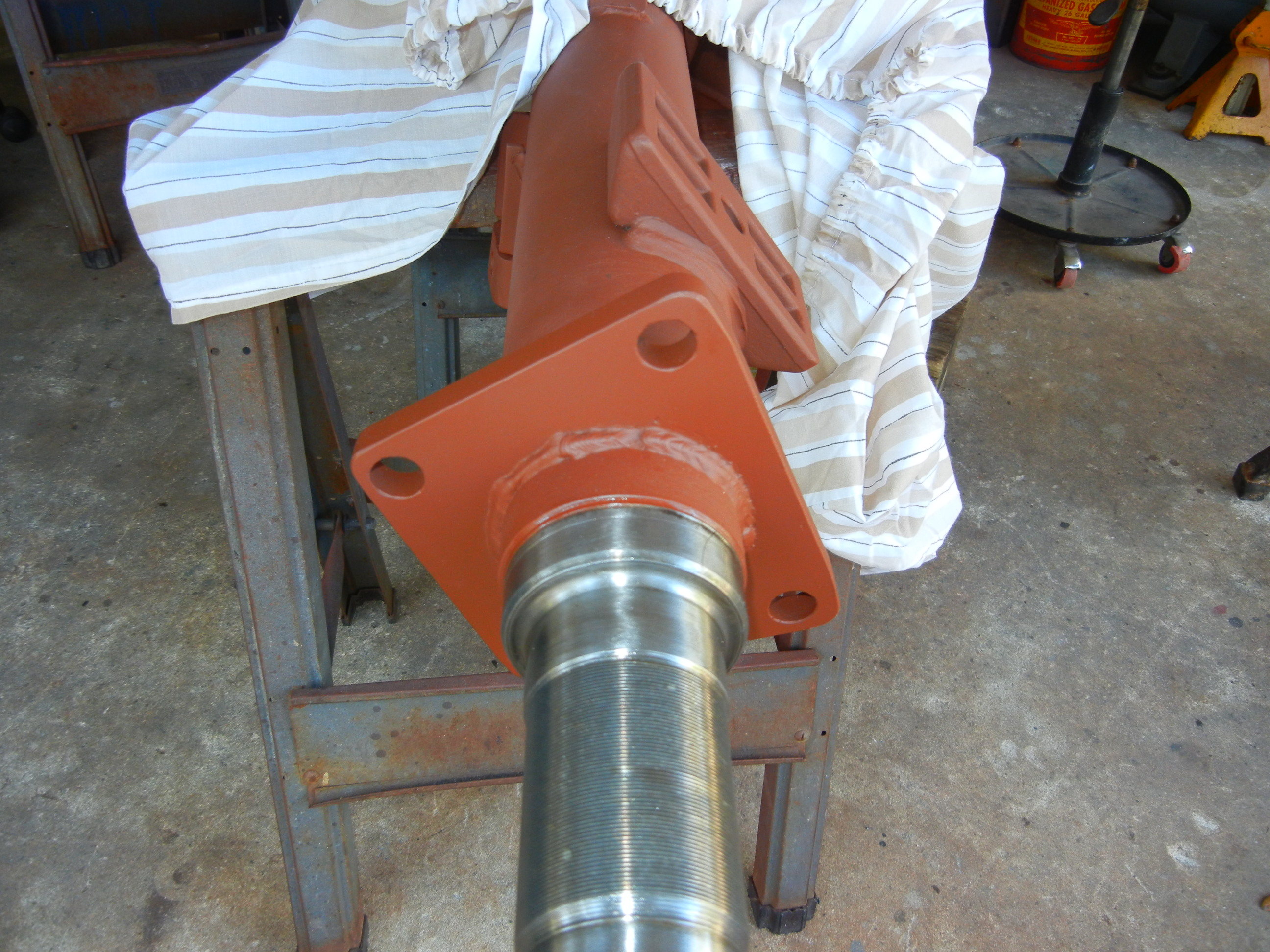
After the setup was finished, the flanges were tack welded and checked
again. Unlike the Sterling, I wanted these flanges welded on both sides to
the tubes for extra strength. This was possible because the outside weld
will not interfere with the brake bracket since the original design used a
larger axle tube.
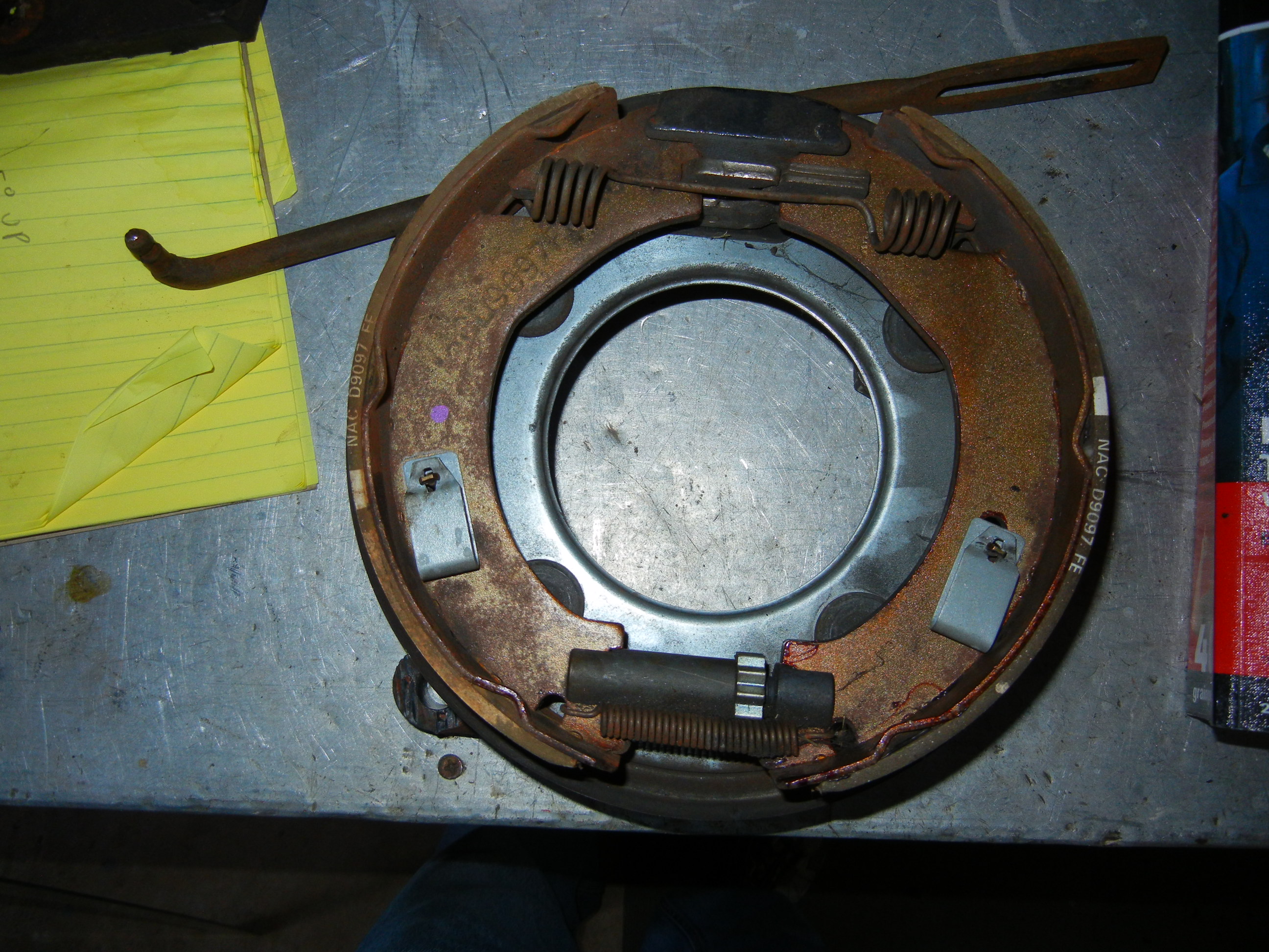
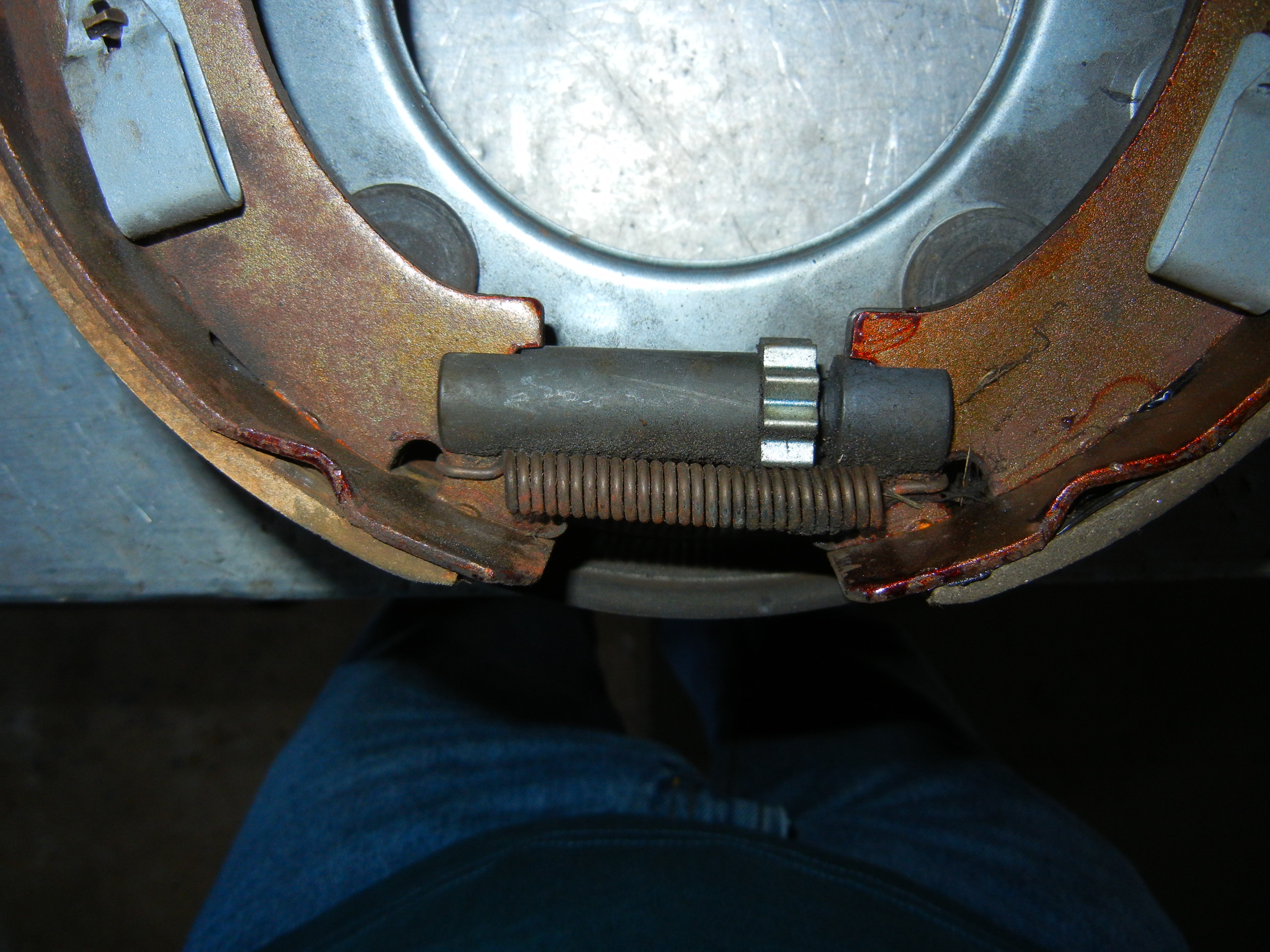
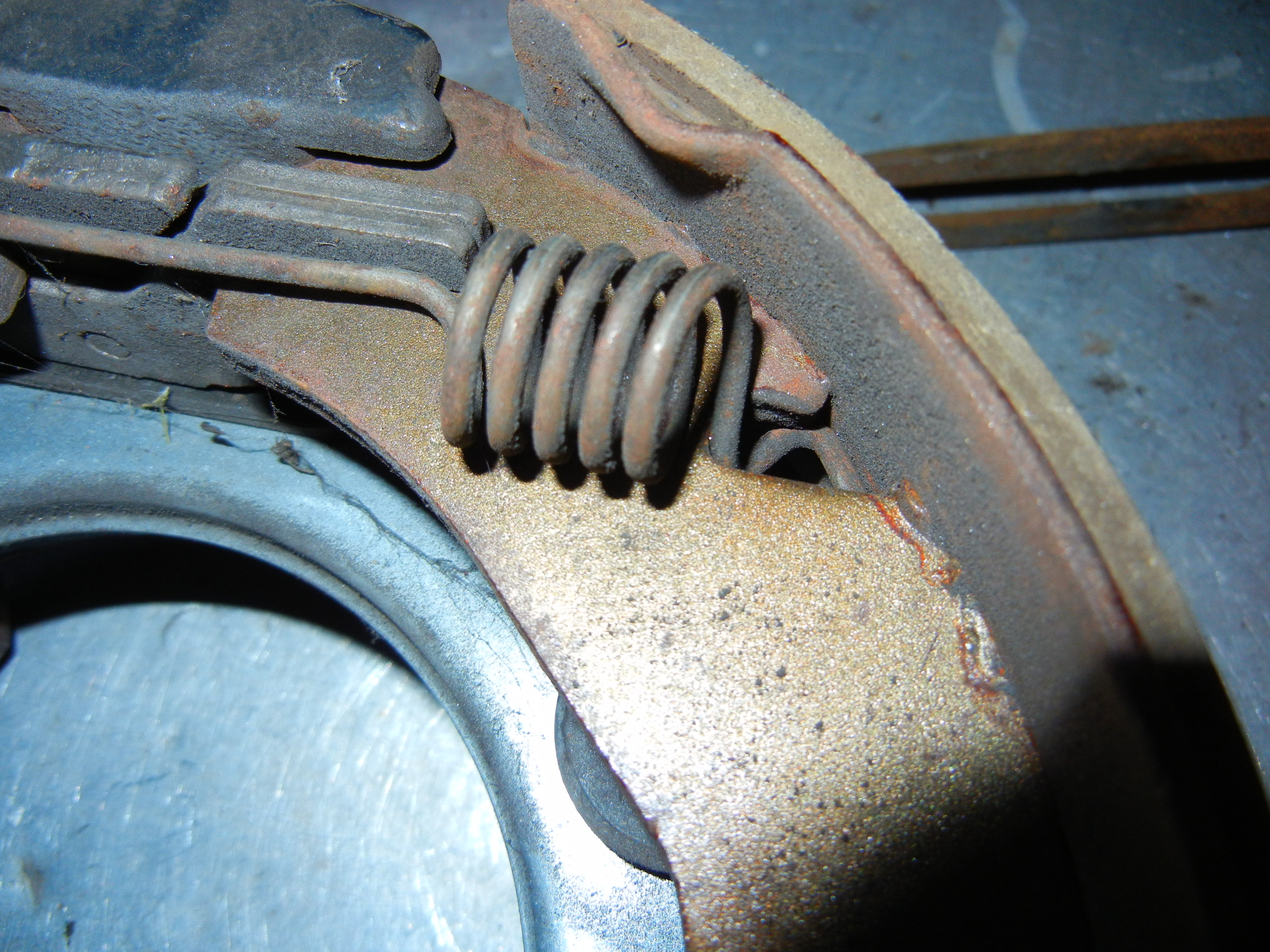
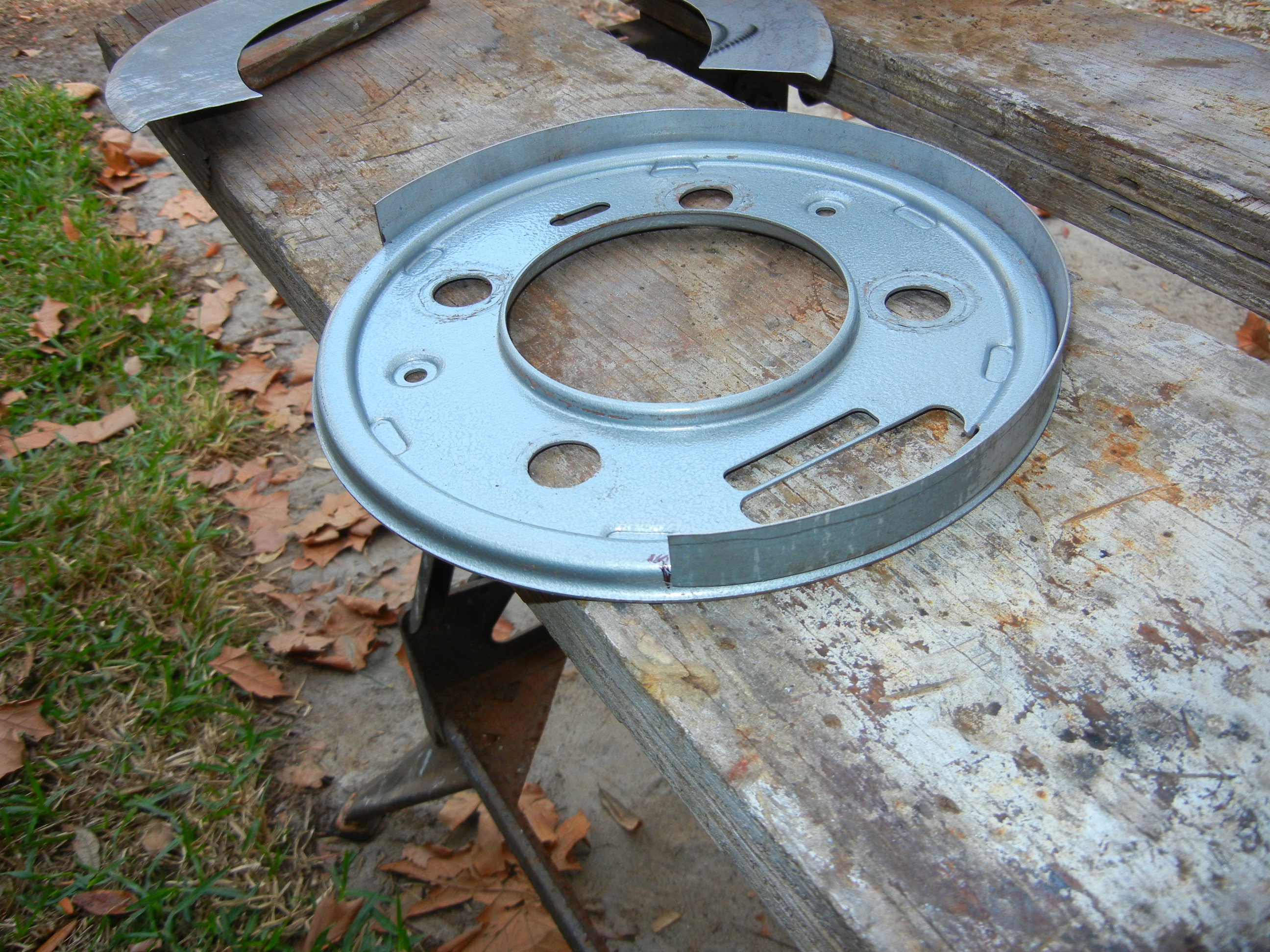
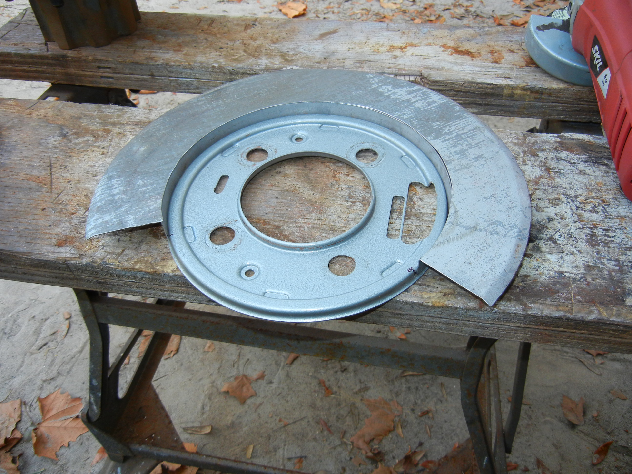
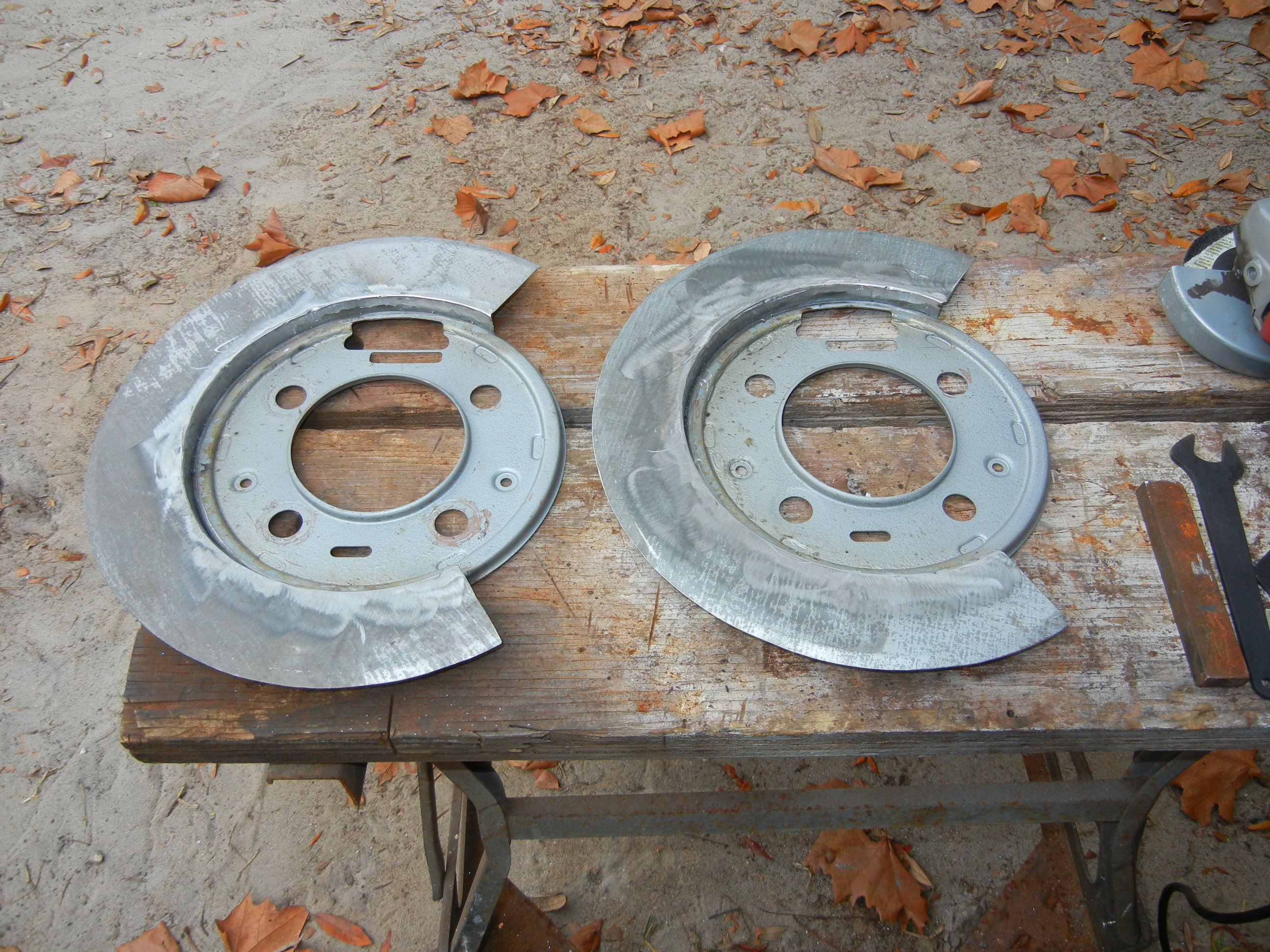
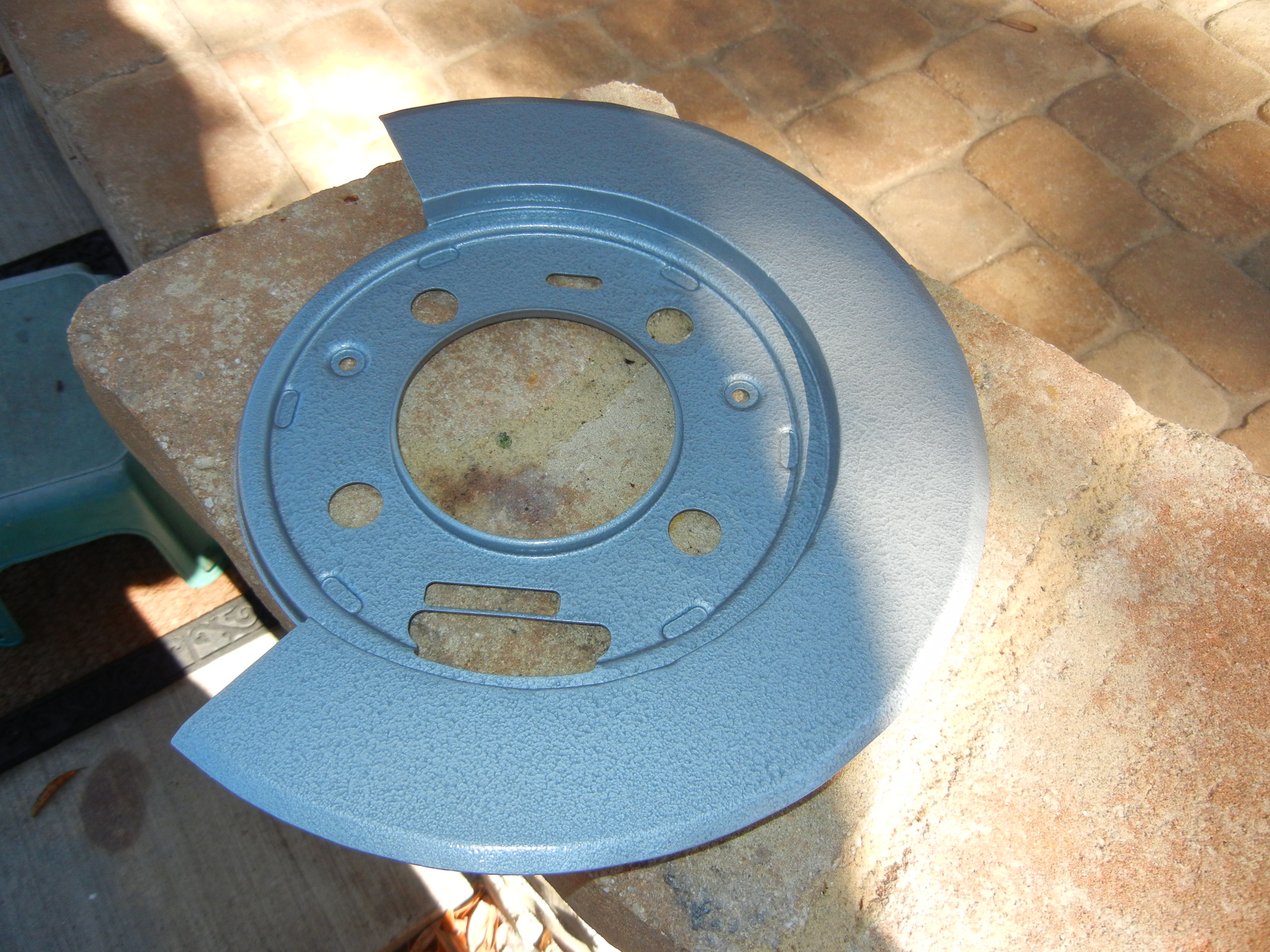
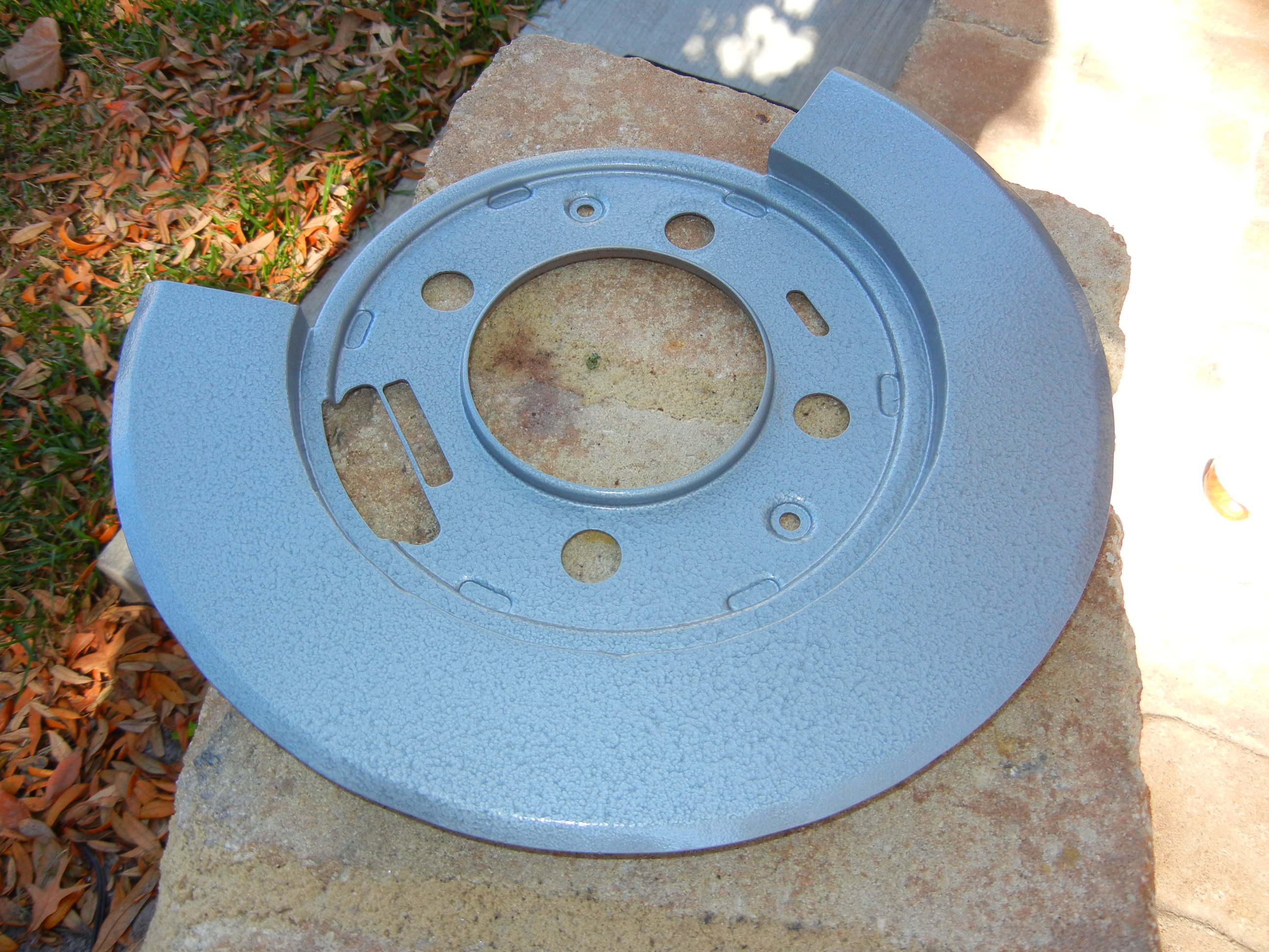
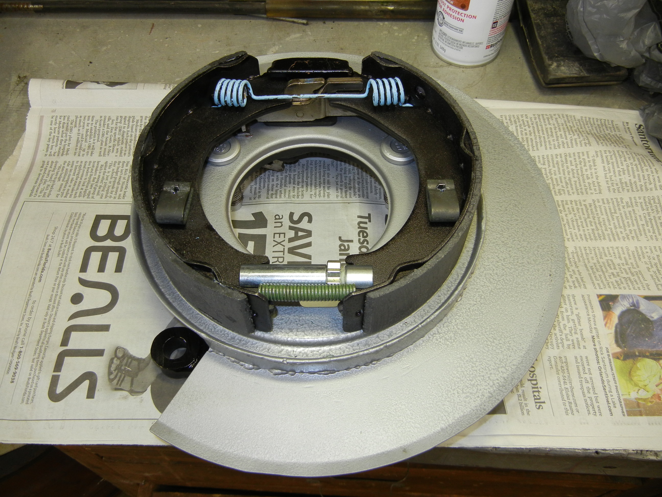
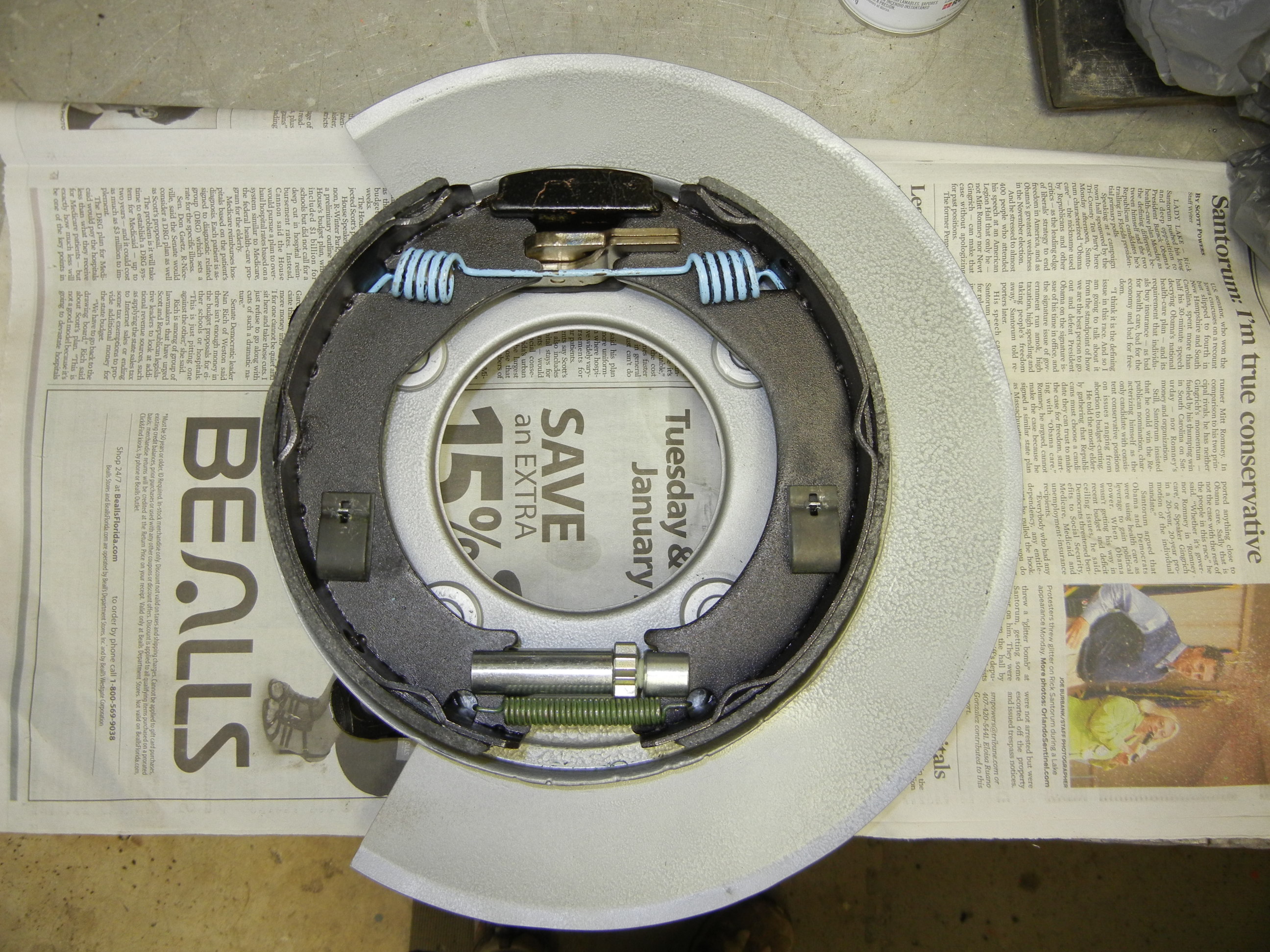
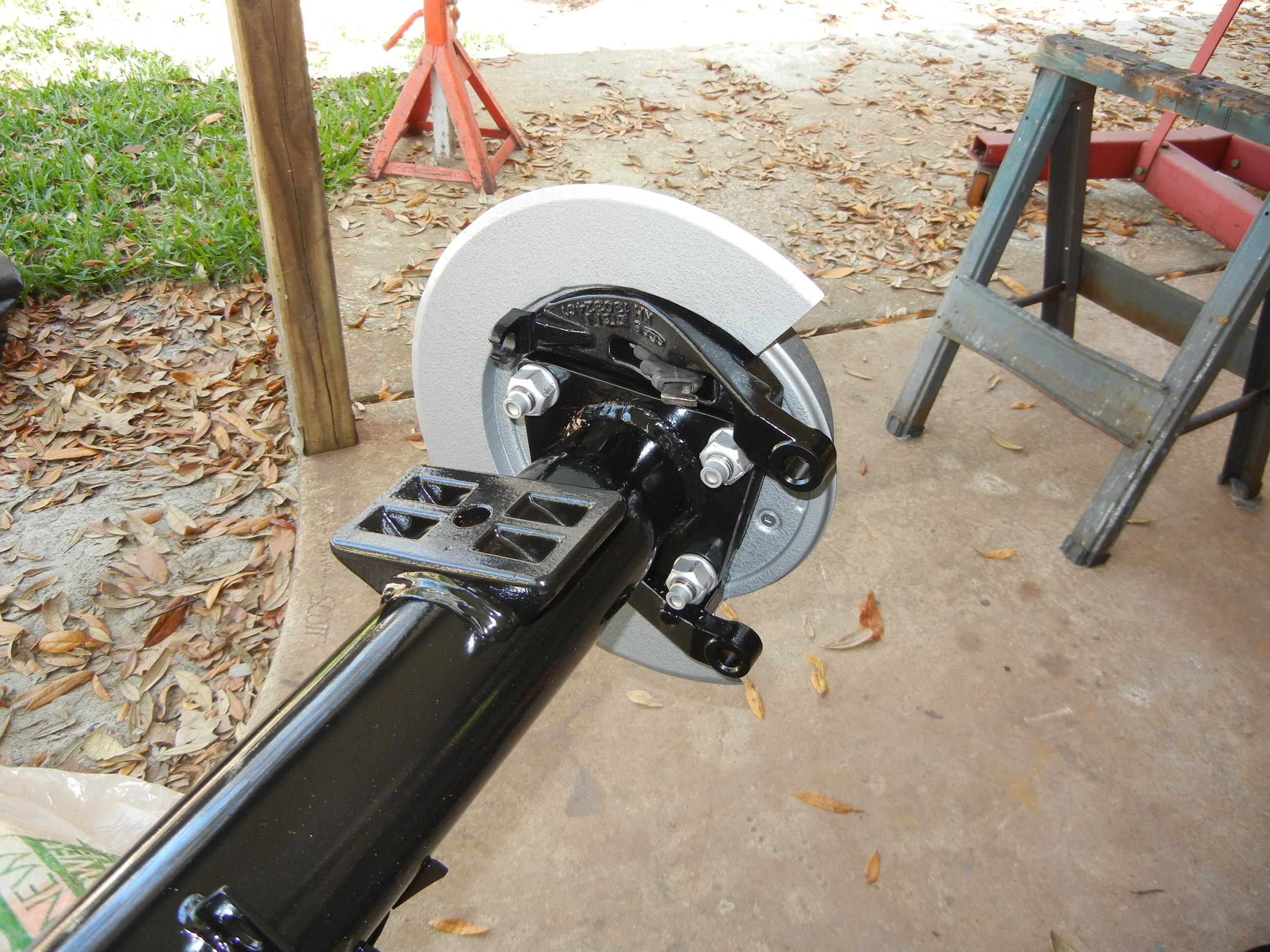
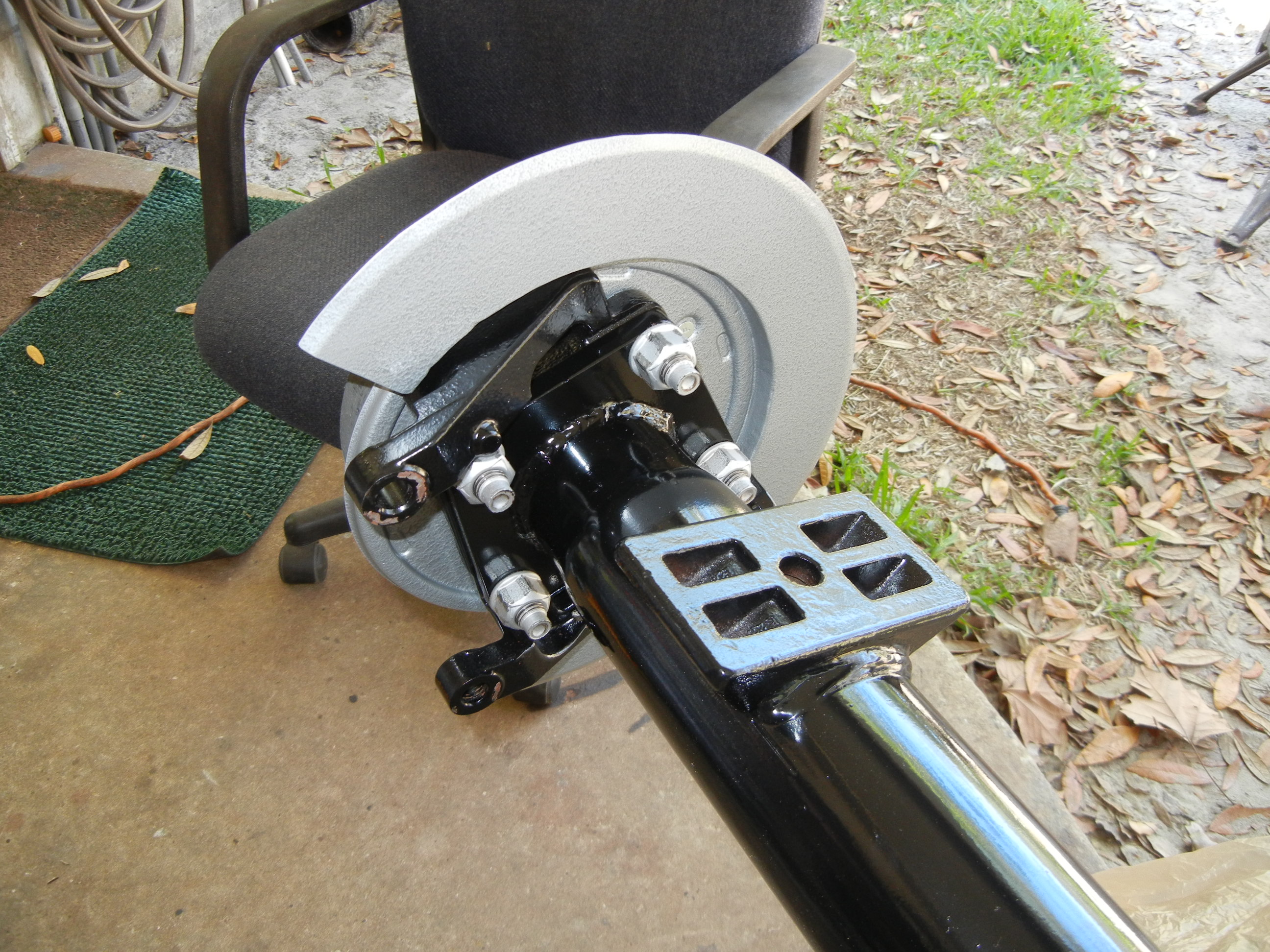
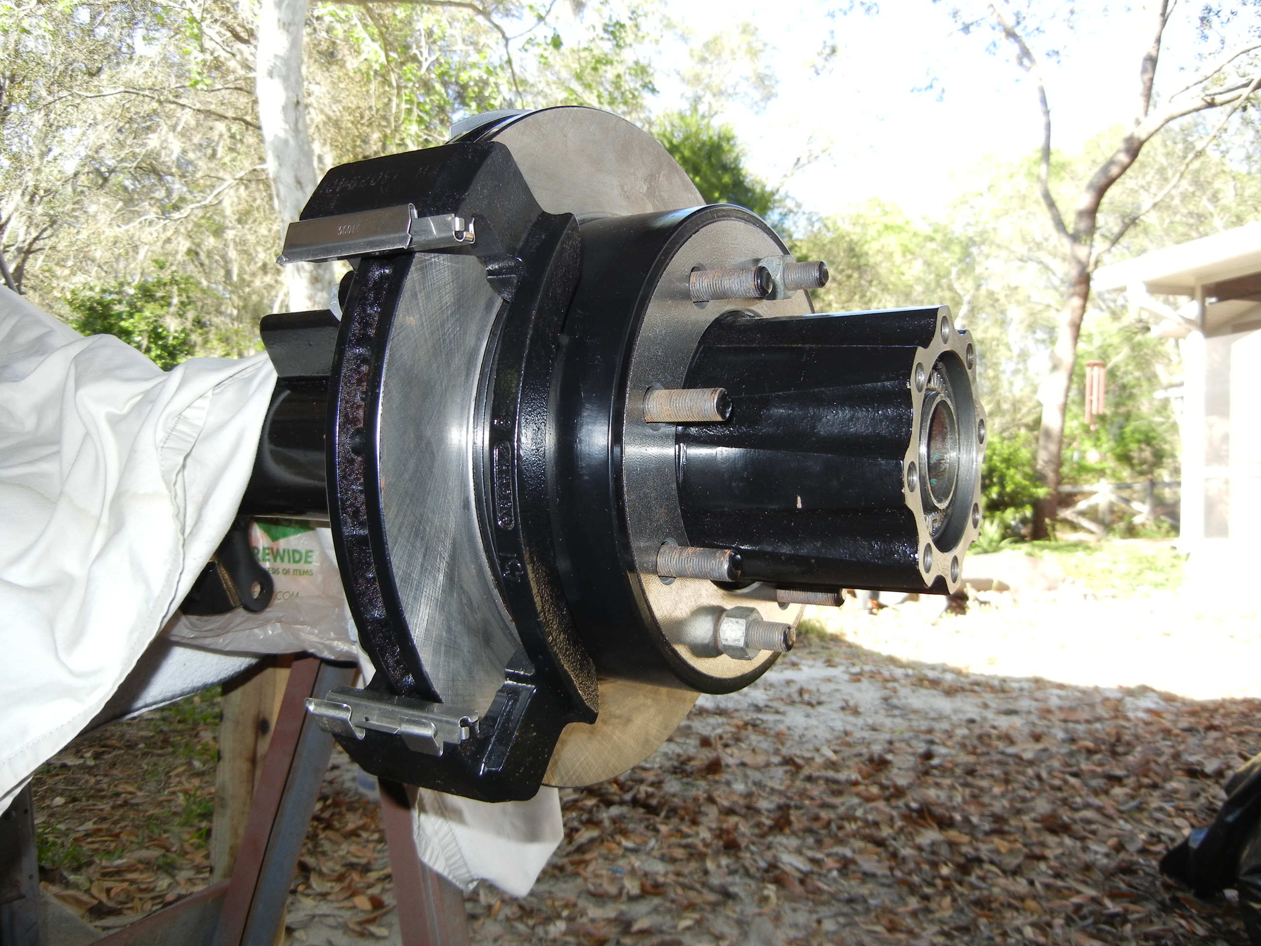
Not happy with the fact the vans did not receive disc splash shields, we set
out to make our own. My father made a separate shield for his Sterling but
came up with a simpler idea for this build. He just added some sheet steel
to the original P-brake drum backing plates which will wrap around the disc
like the Super Duty design.
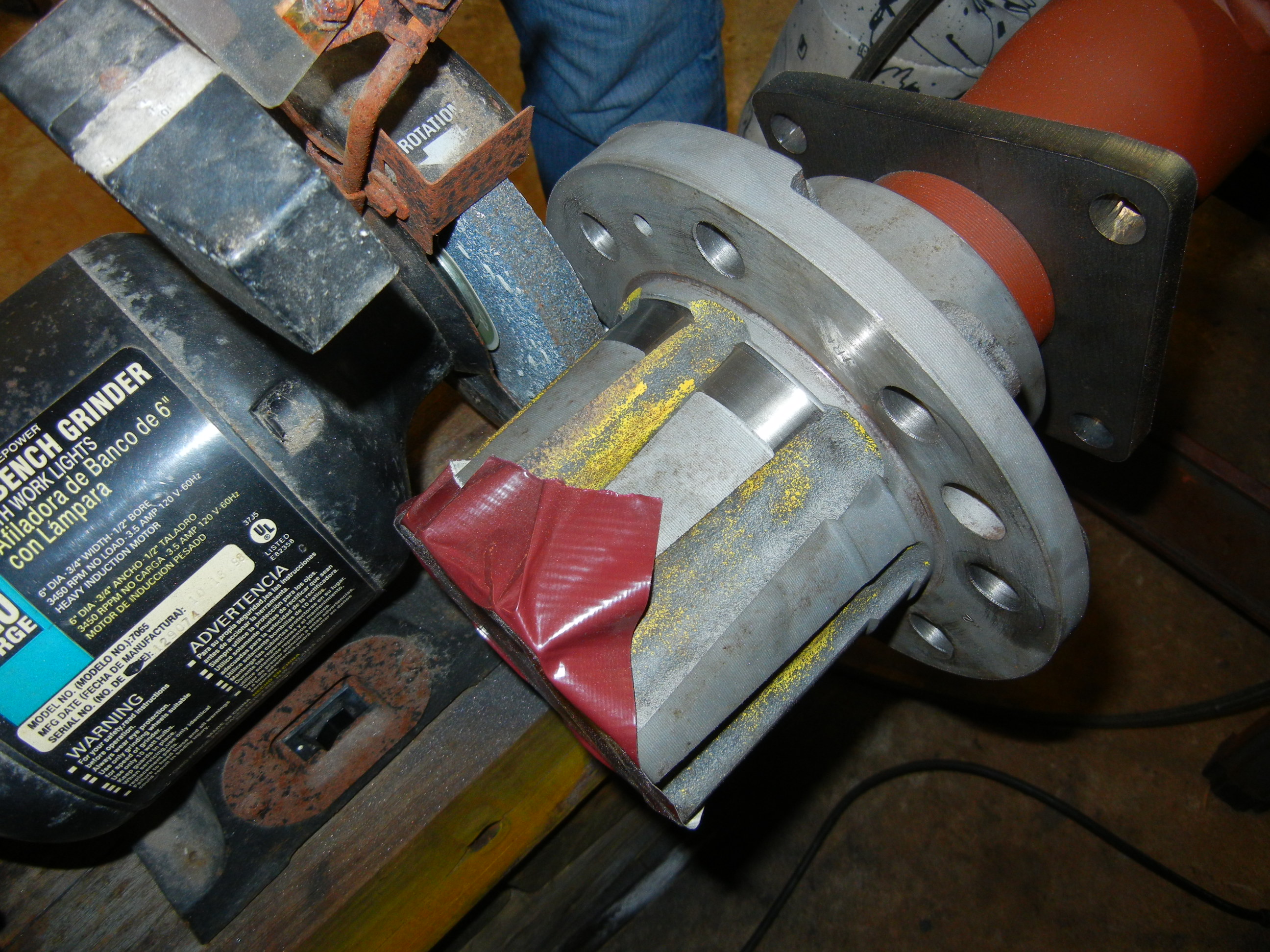
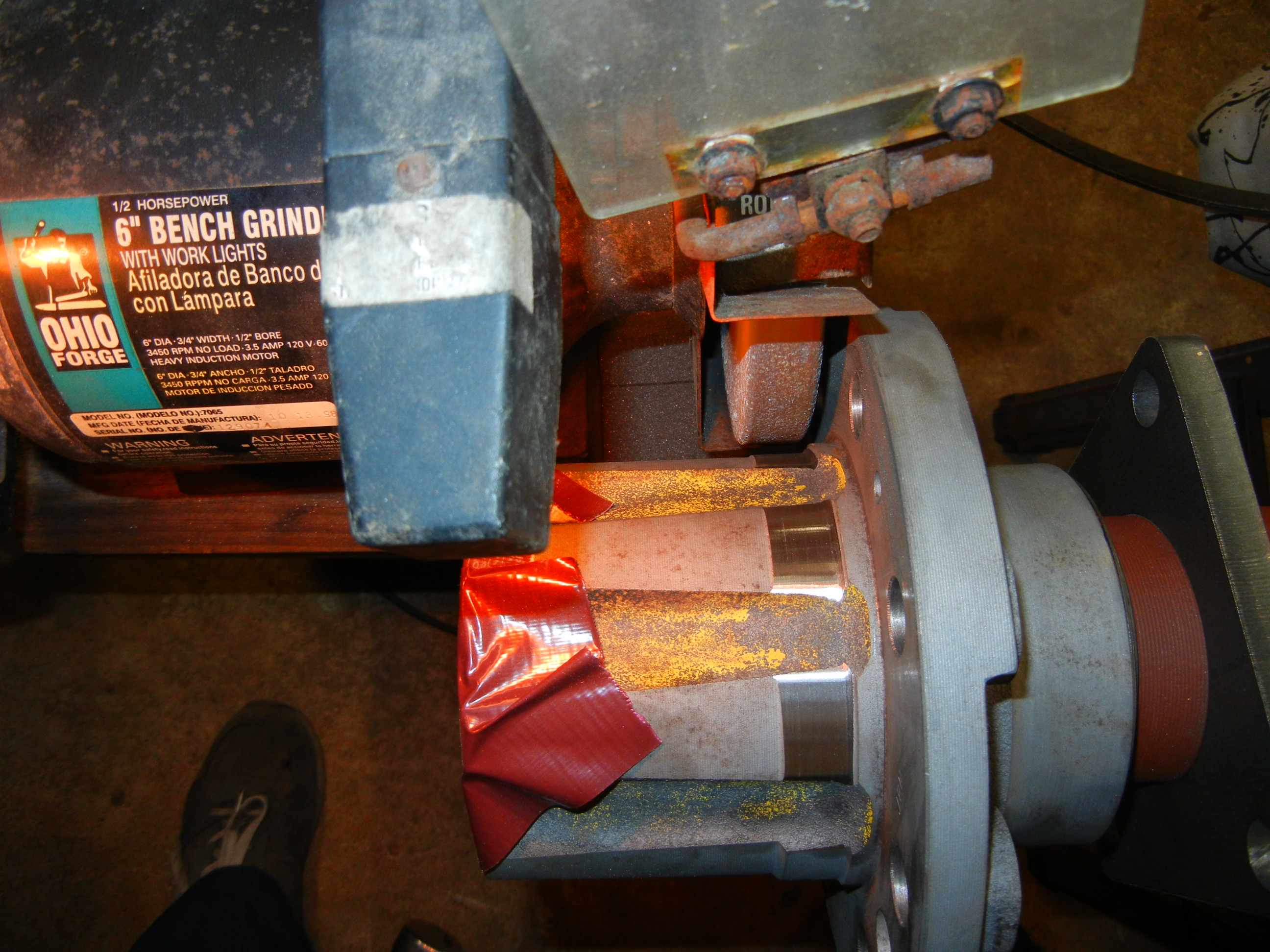
One other set back we had was the extra rib on the D60 hub and would not let the vintage 1970's wheel go over. Again my father to the
rescue came up with a simple solution: hold up a spare bench grinder we had
laying around to the hub and simply grind away the extra material!
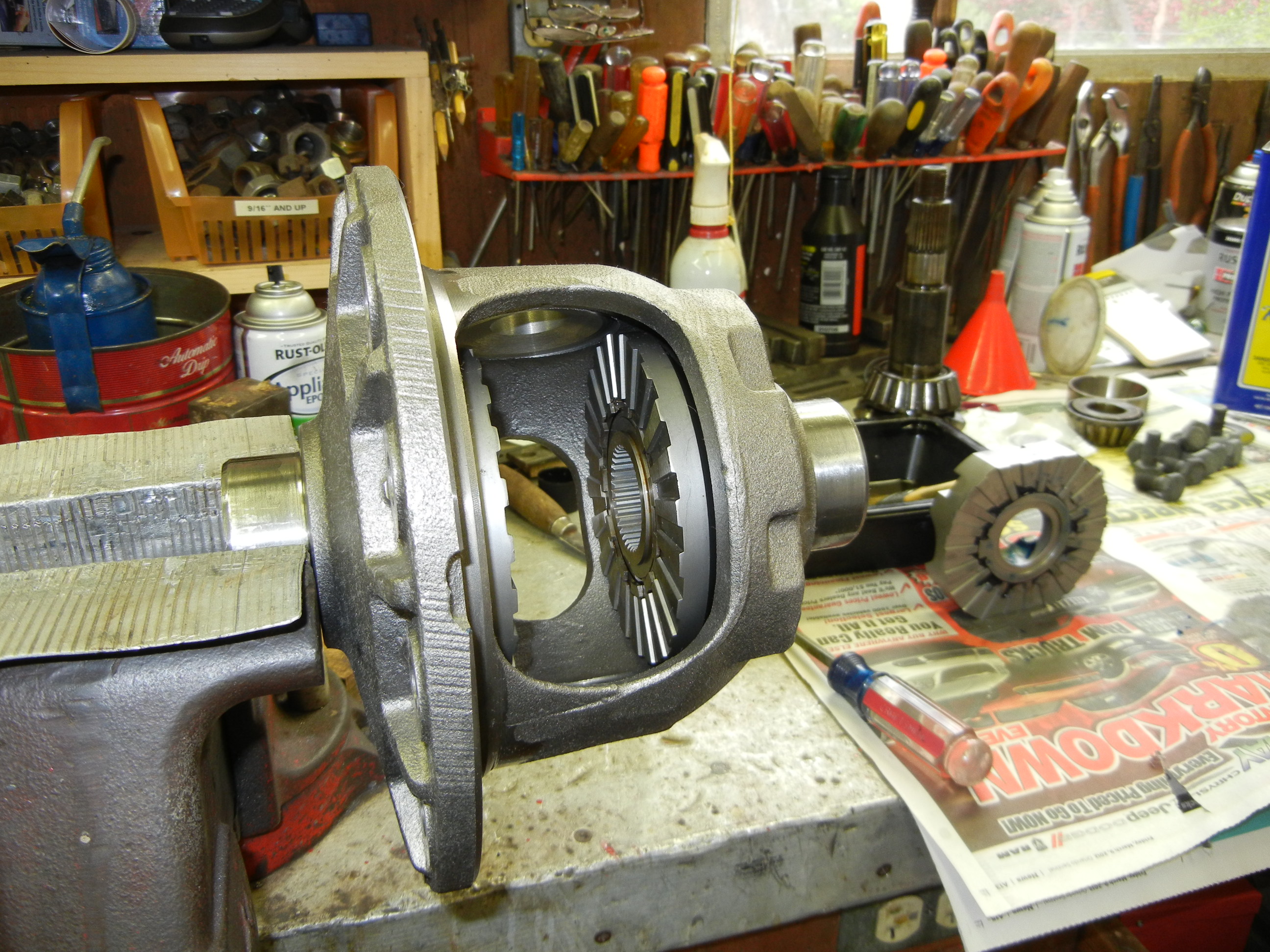
Now that the brakes are wrapped up, it is time to finish the internals.
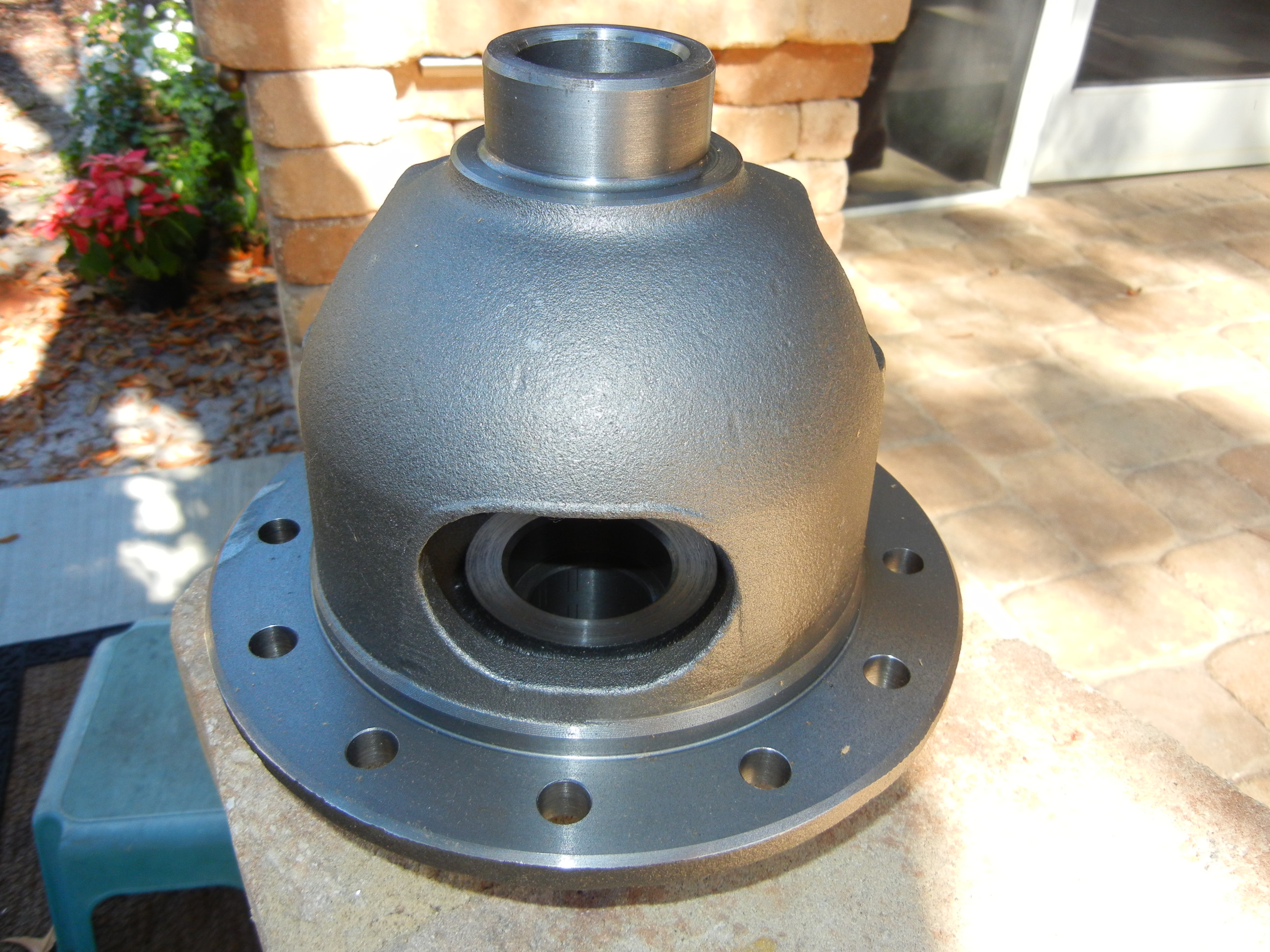
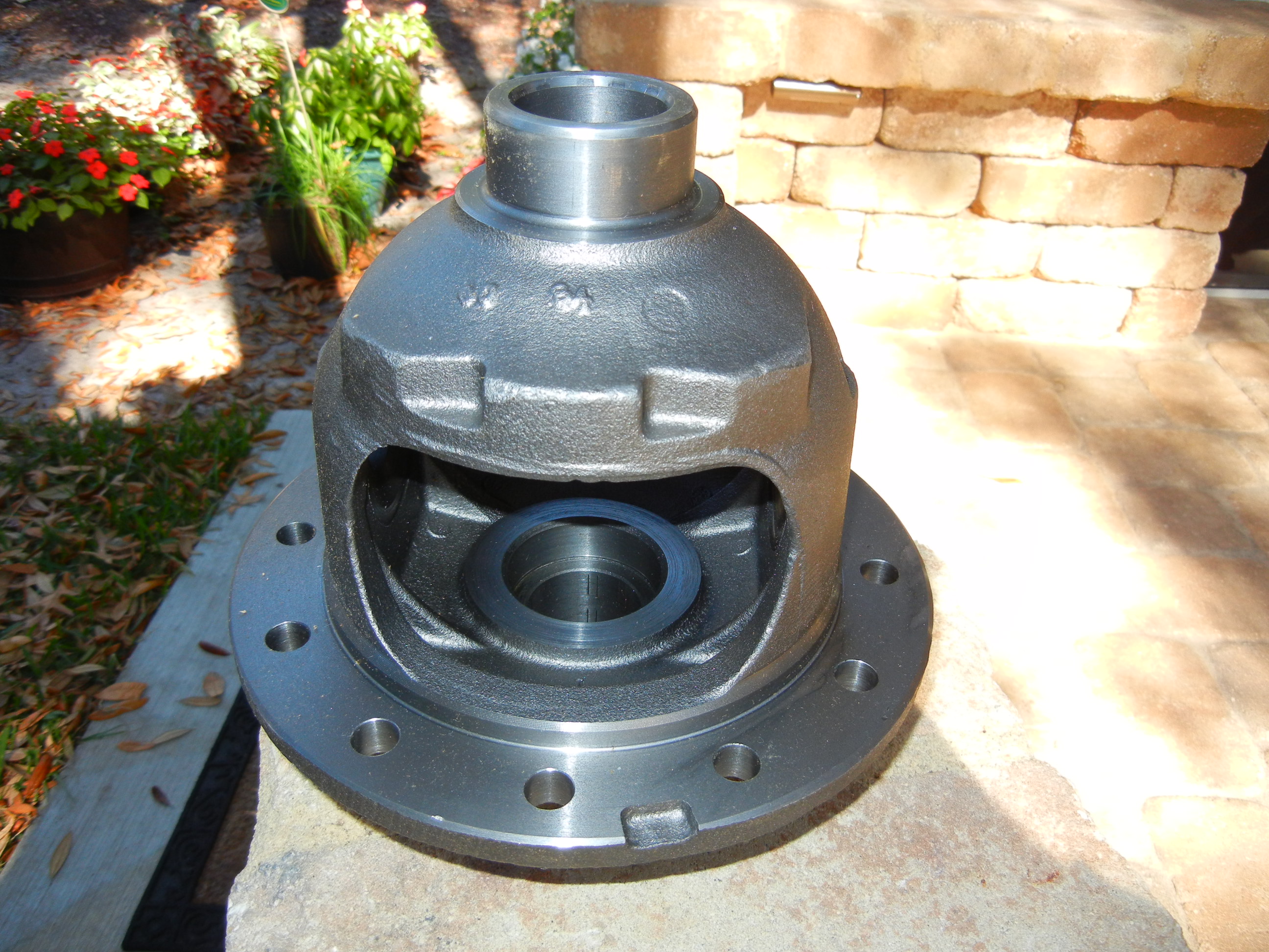
Since I want 4.88 gears, a new 4 series carrier was needed. I ordered a new
Dana/Spicer open carrier on eBay. This will get stuffed with the Powertrax
No-Spin locker.
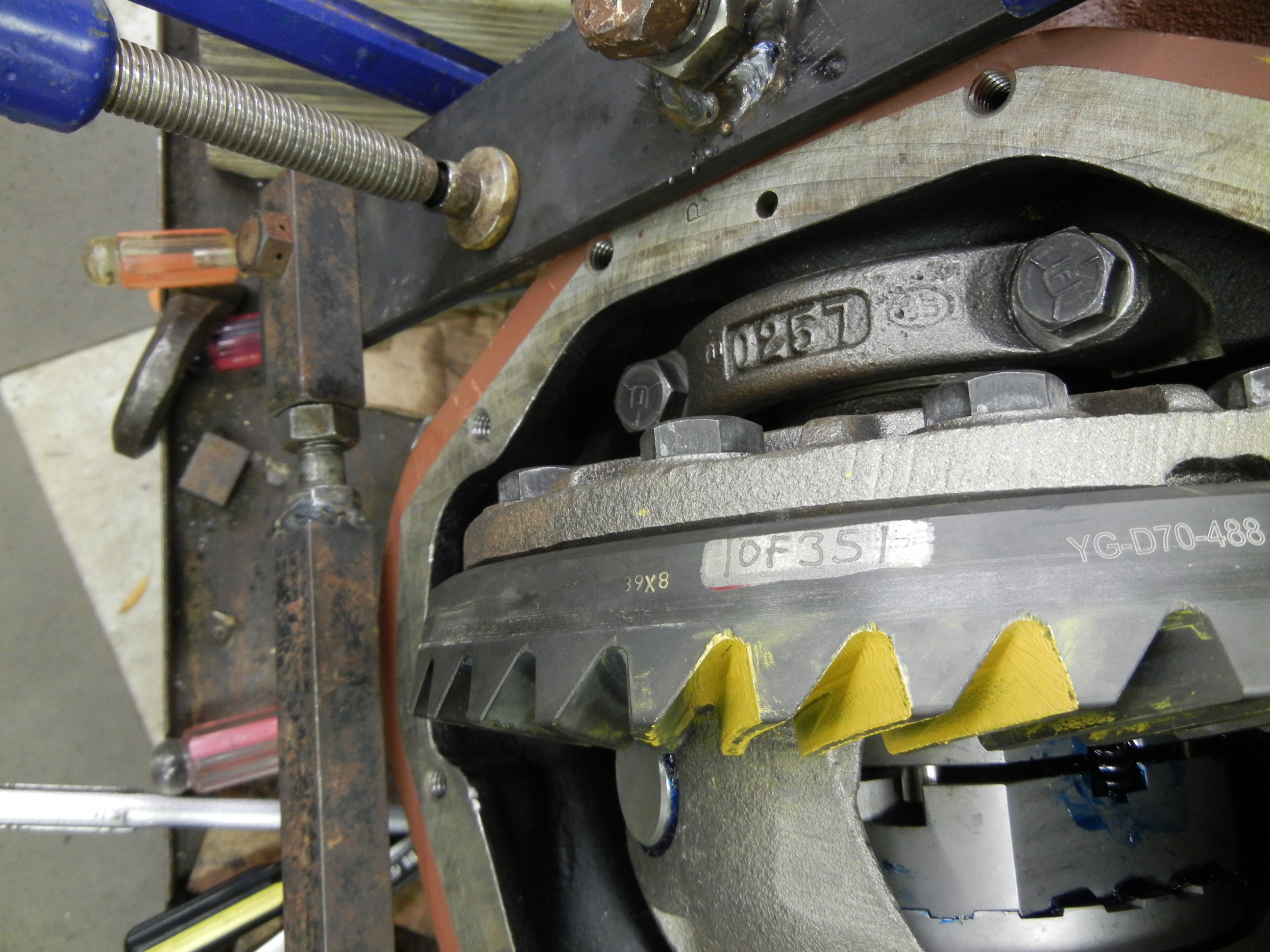
Finally after more than a month working on the frame, we are now back on this
axle build. The 4.88 gears from Superior Axle and Gear showed up. They don't say
where they are made. I think they are made overseas somewhere. However, there is
a YG part number stamped on the ring. Maybe this means Yukon Gear? I thought
they just rebadged other products. Who knows. Anyways, when building any Dana
axle, you should invest in setup bearings that slip on easily in order to
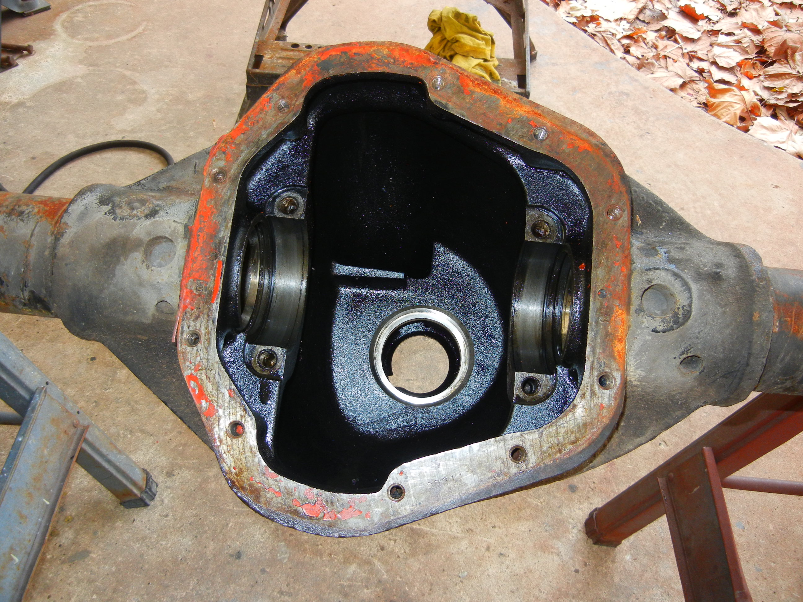
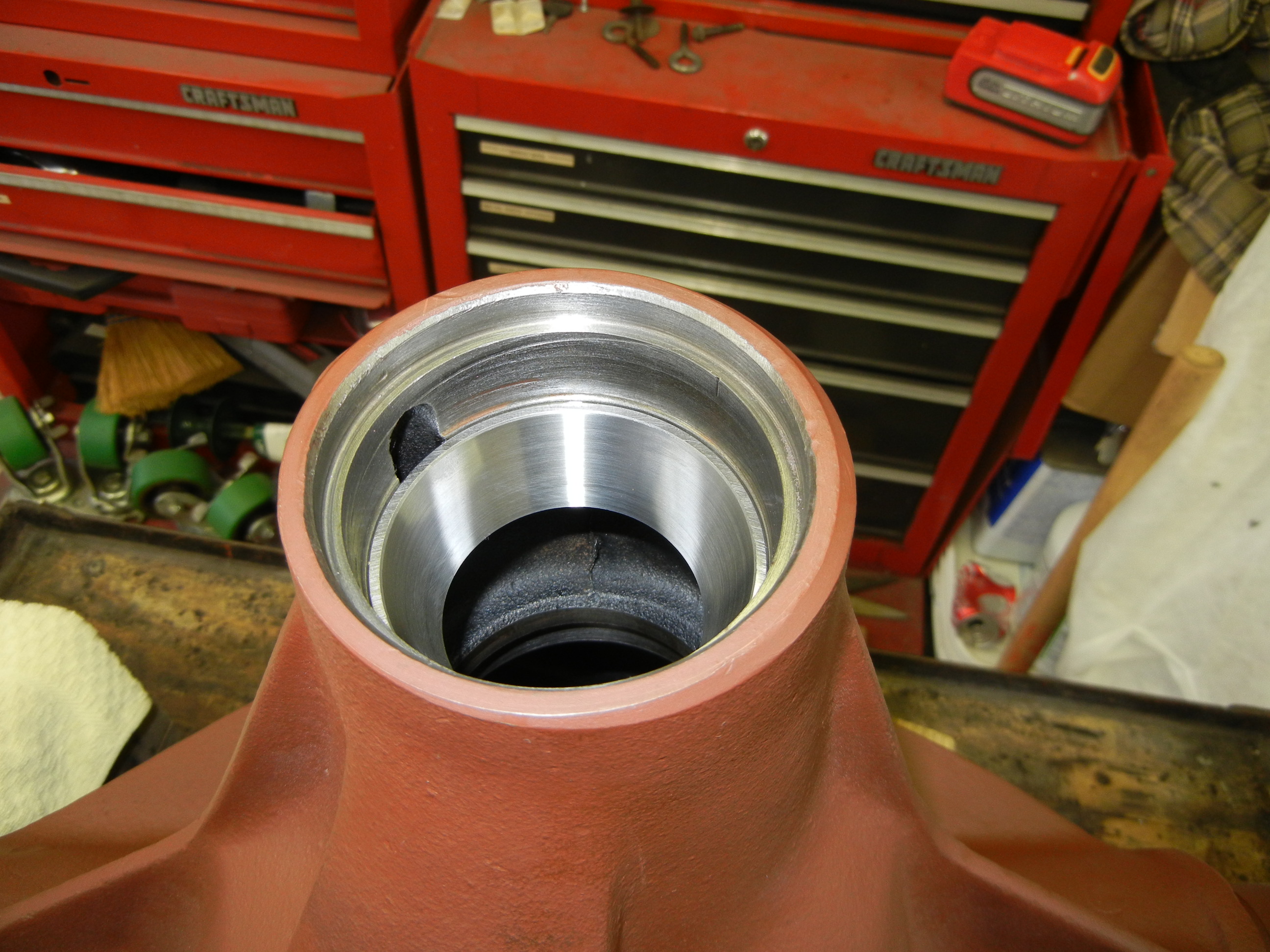
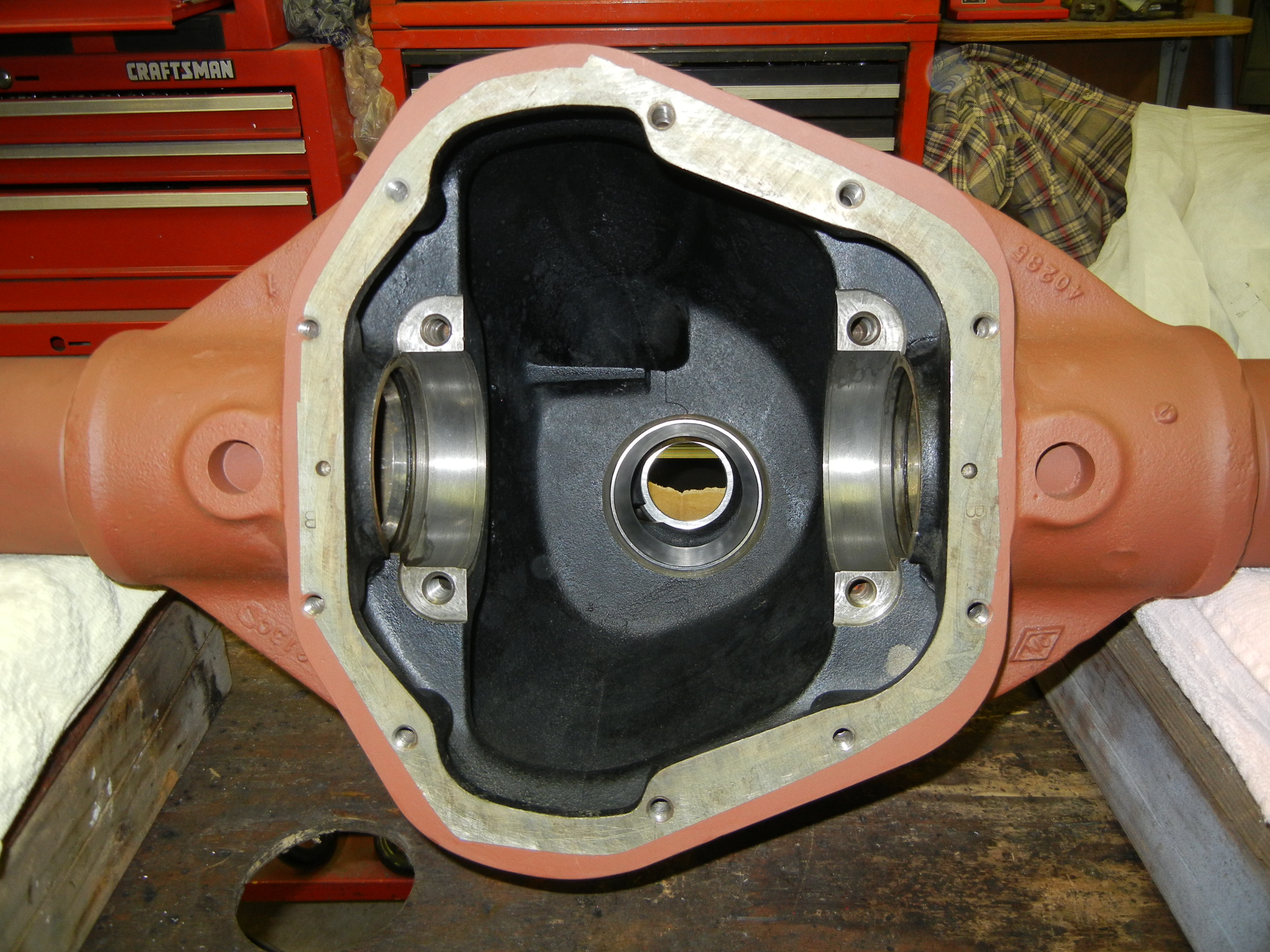
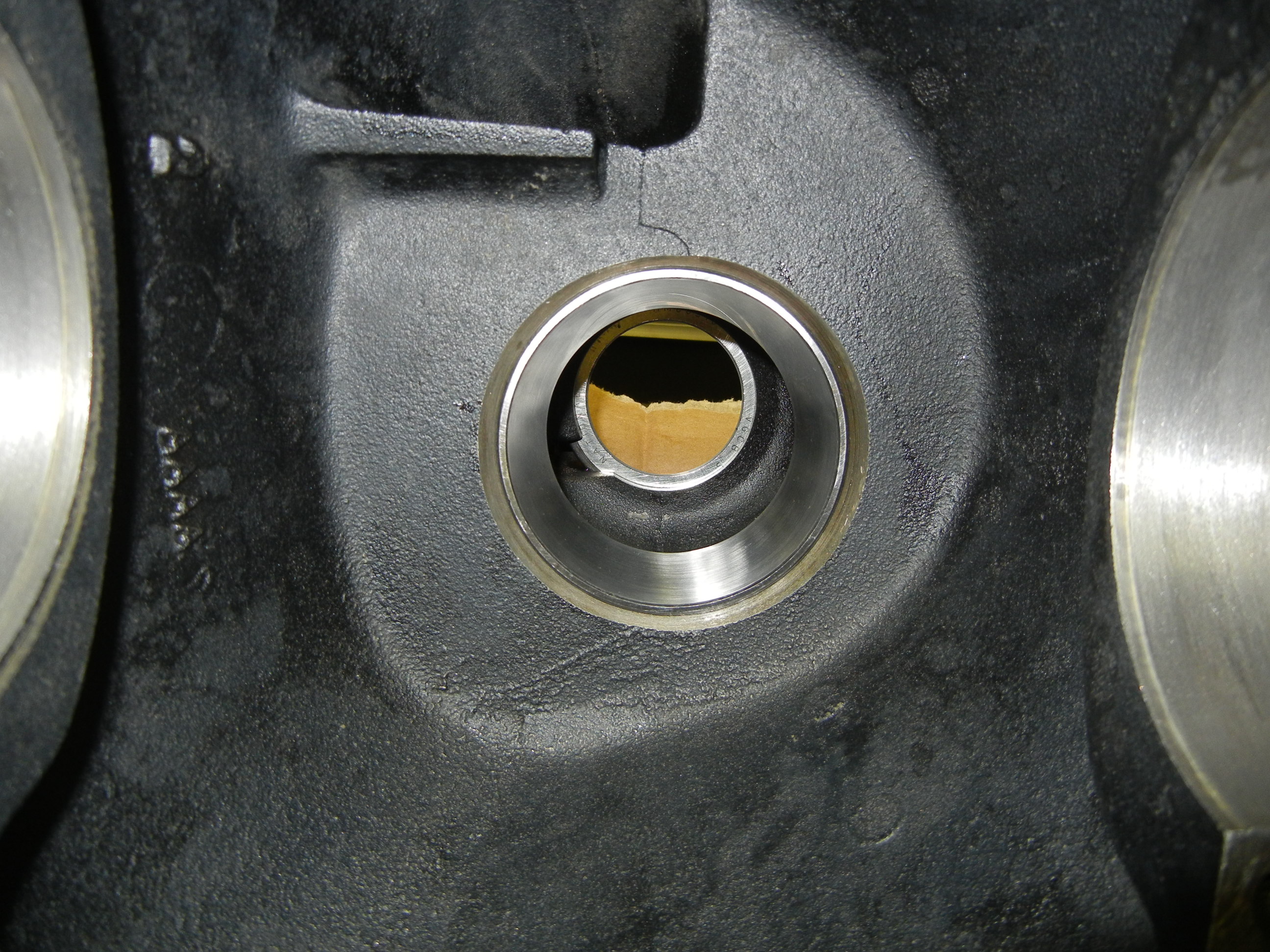
facilitate shim changes easily. The first order of business was to clean the
housing again, press in the outer pinion race/cup, press on the new inner pinion
bearing/cone and also prep the new 4 series
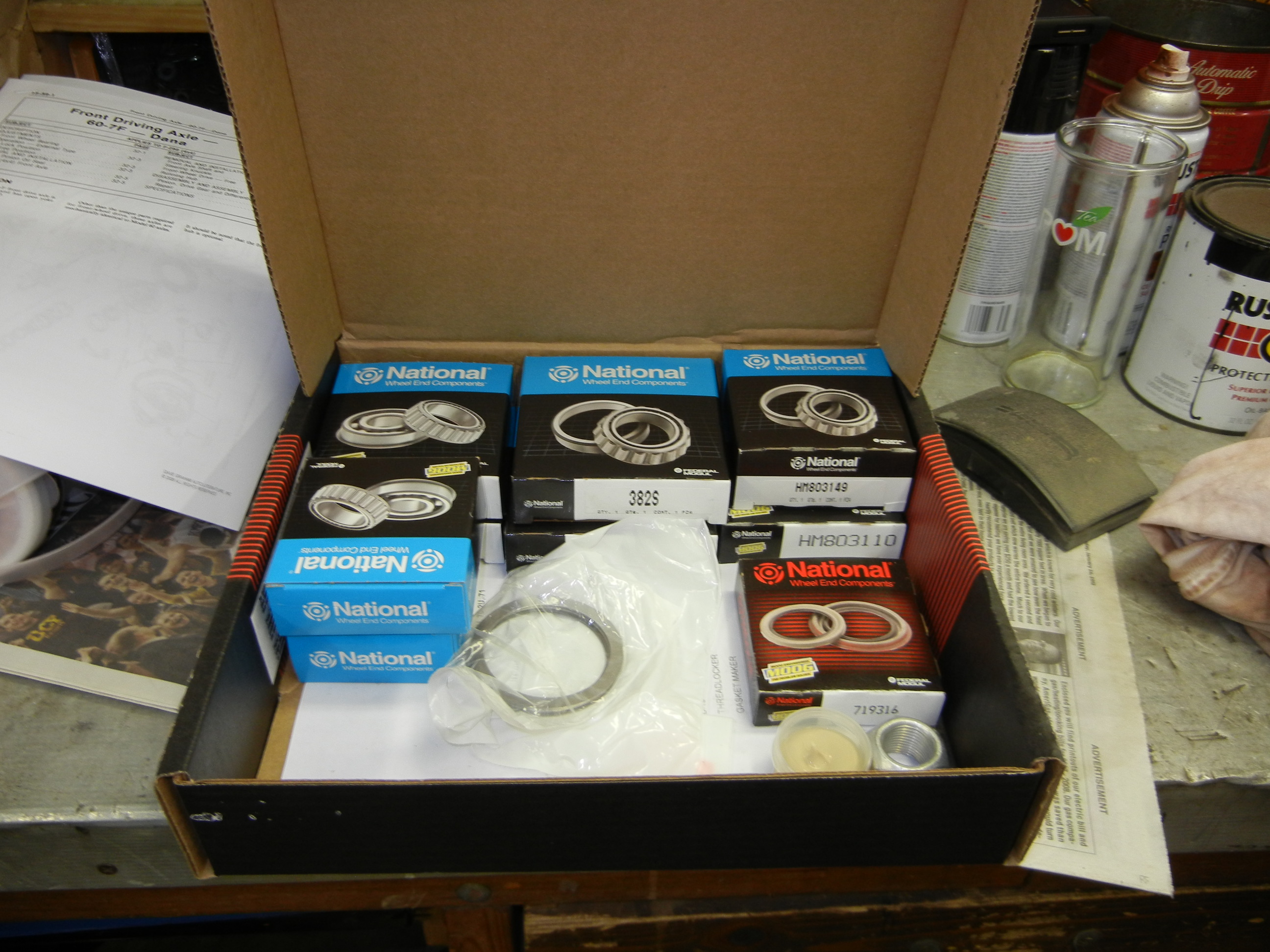
carrier for the Powertrax No-Slip locker. A full center rebuild kit was sourced
from Advance Auto Parts. It includes National brand bearings and seals which are
made in China, Spain and the USA.
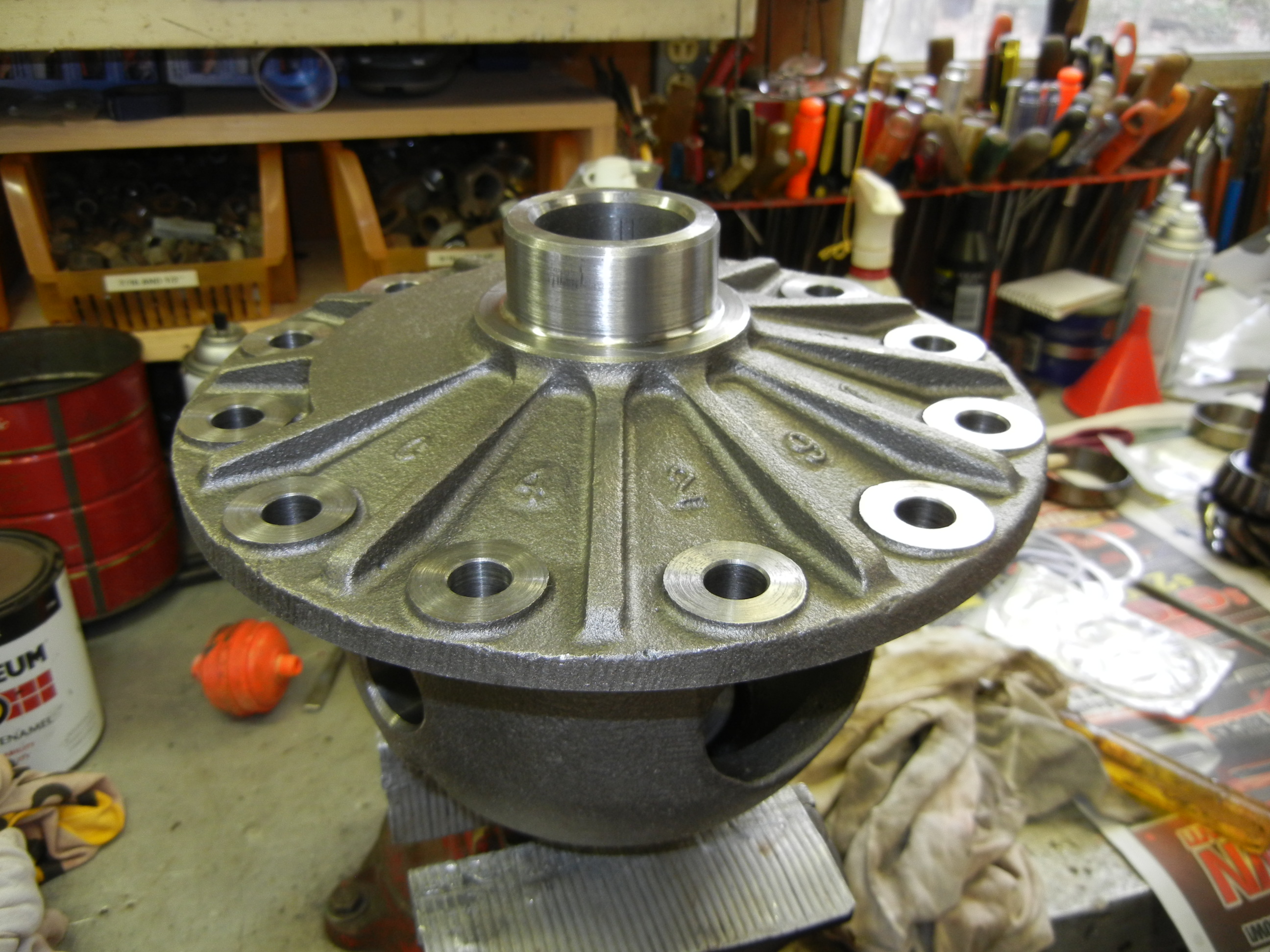
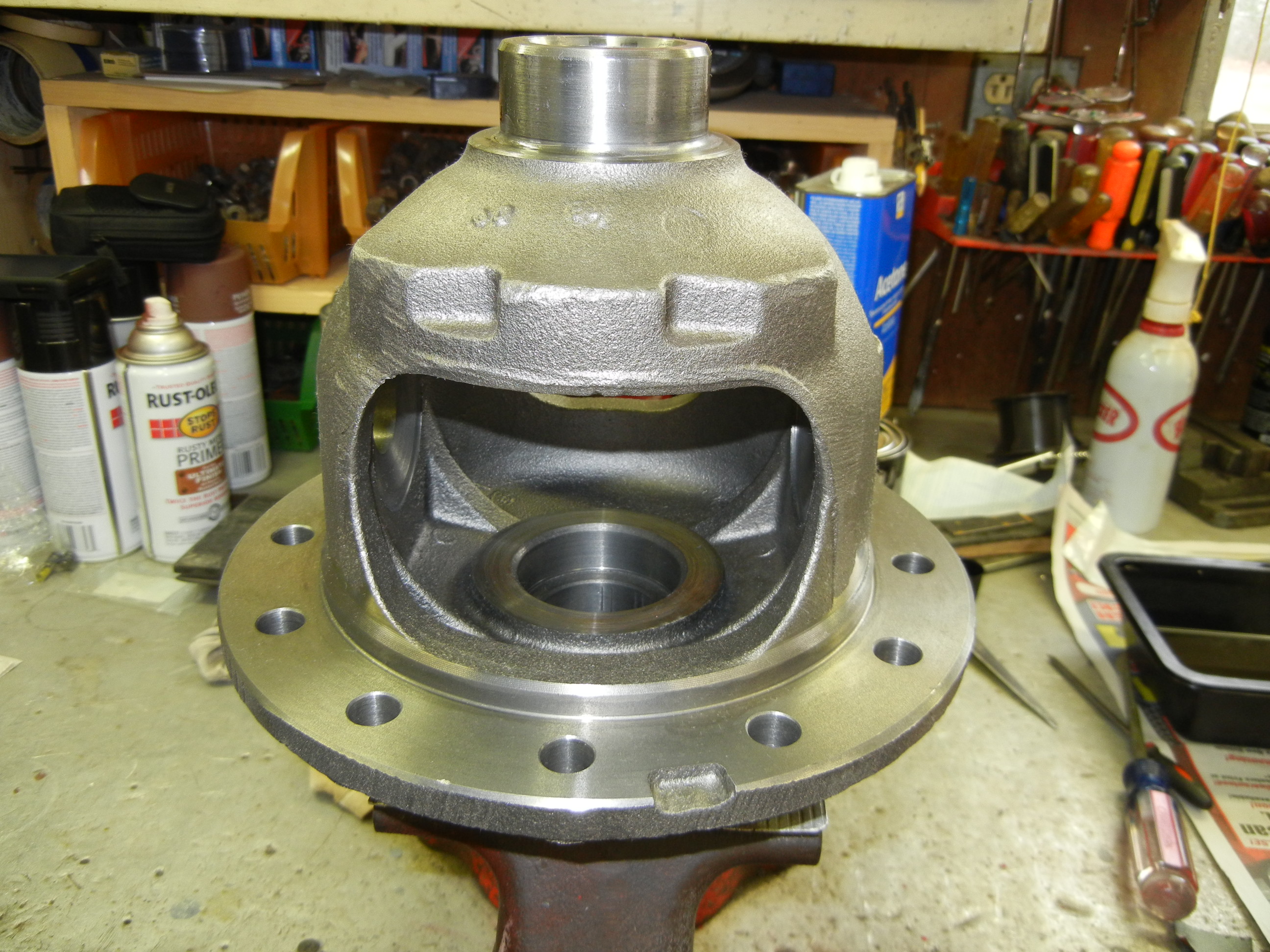
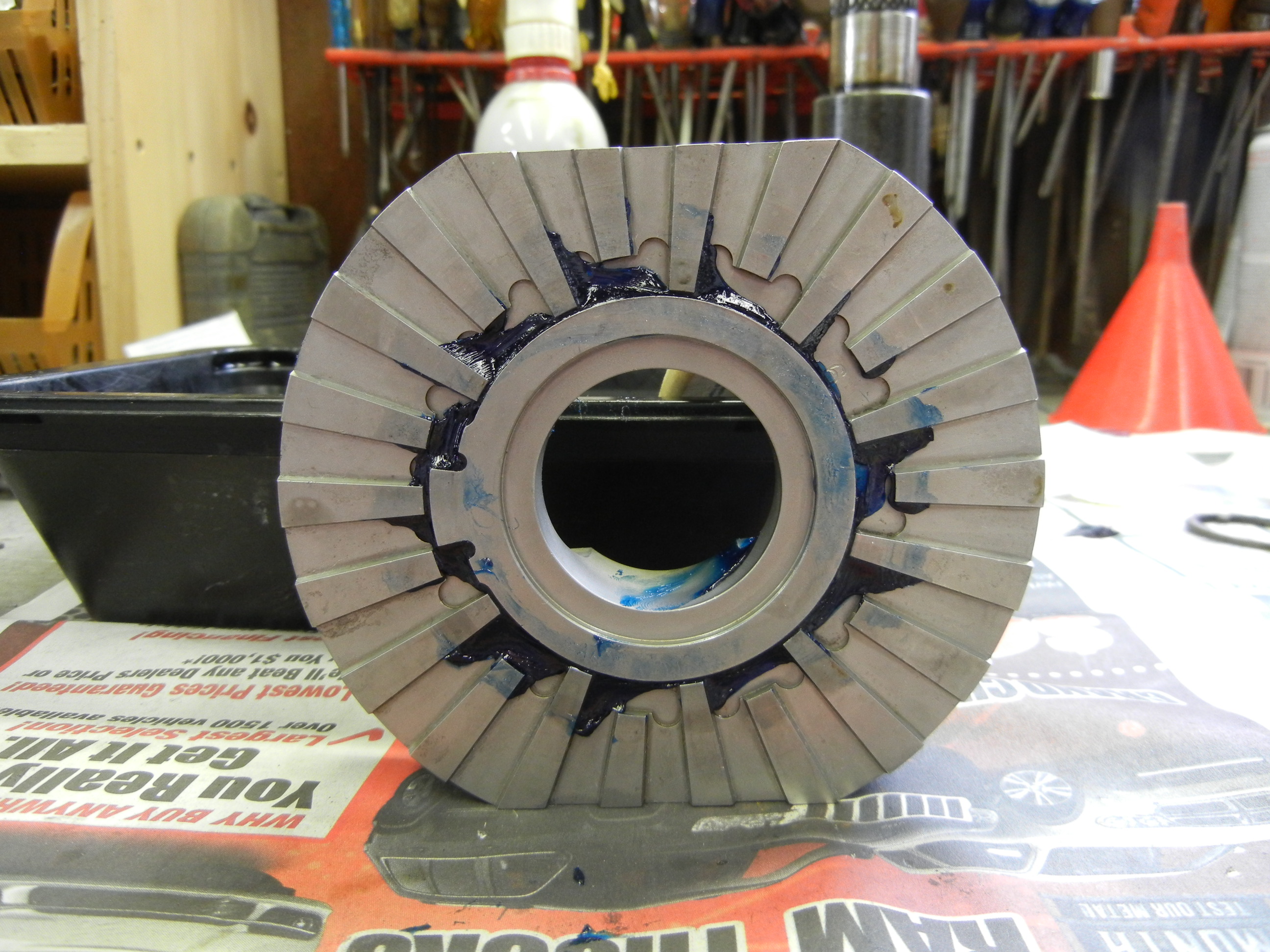
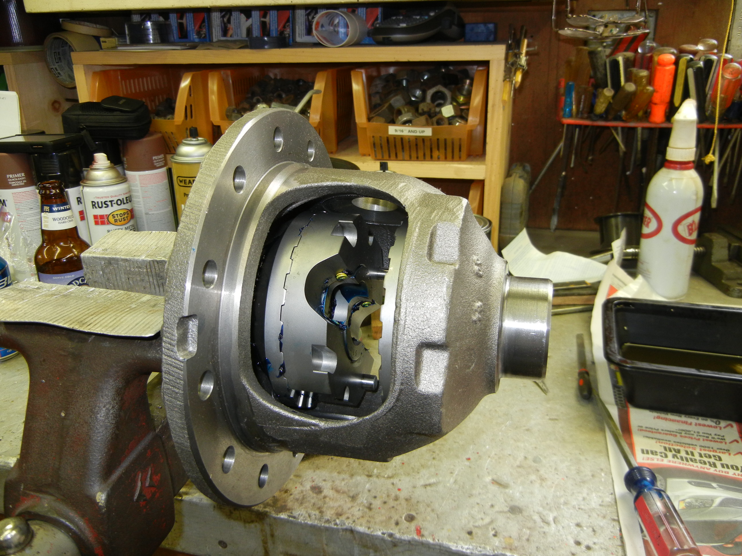
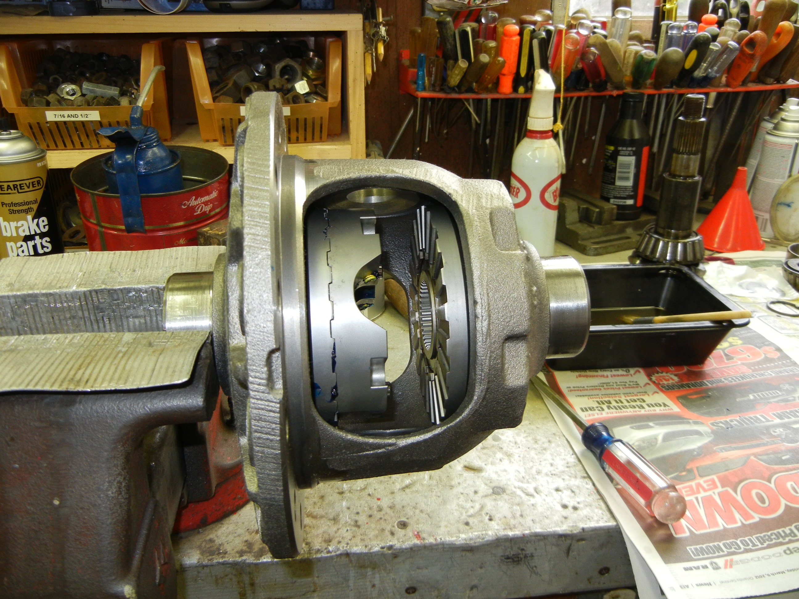
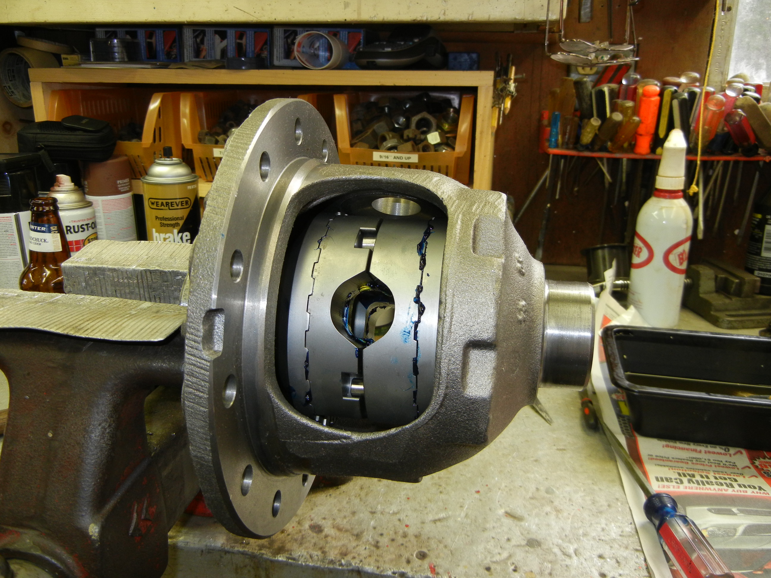
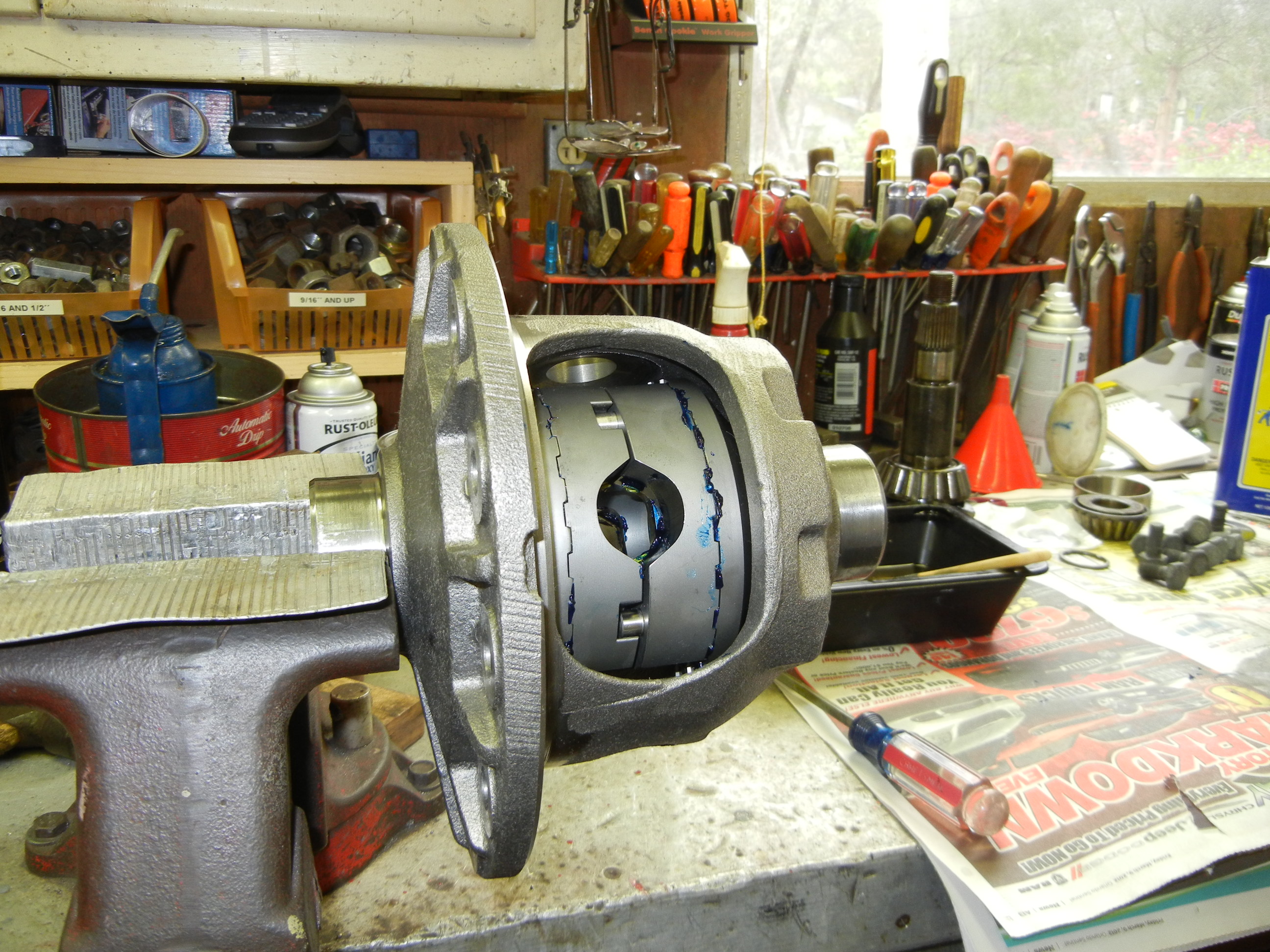
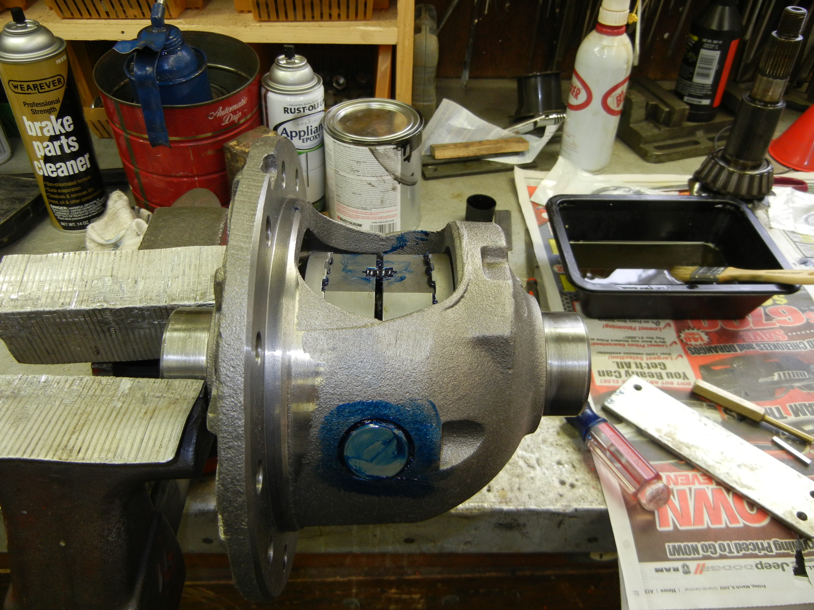
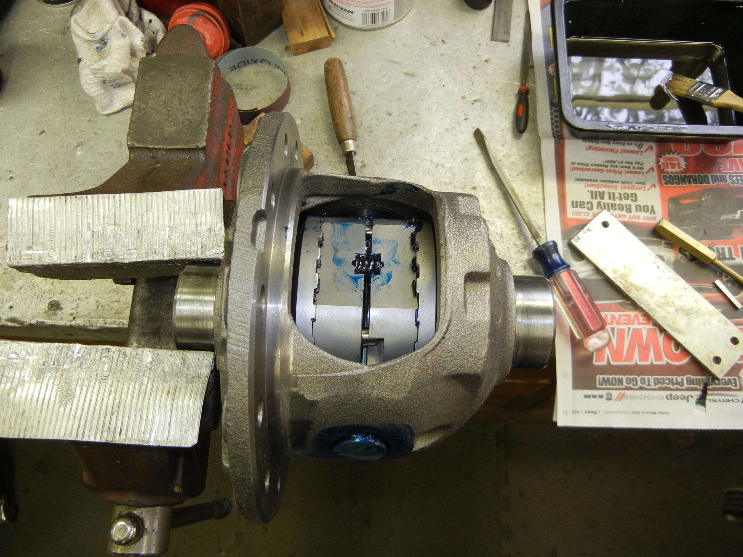
Next we figured the locker would be easiest to install while the carrier was
on the bench. Following the supplied instructions, this was probably the easiest
piece on the truck to assemble.
Next came the ring gear which was also simple to install. The only catch is
that you should never reuse old ring gear bolts. Also use thread lock on the
bolts to prevent them from ever backing out. The shim pack from the old pinion
was used as a starting point behind the new set up pinion race.
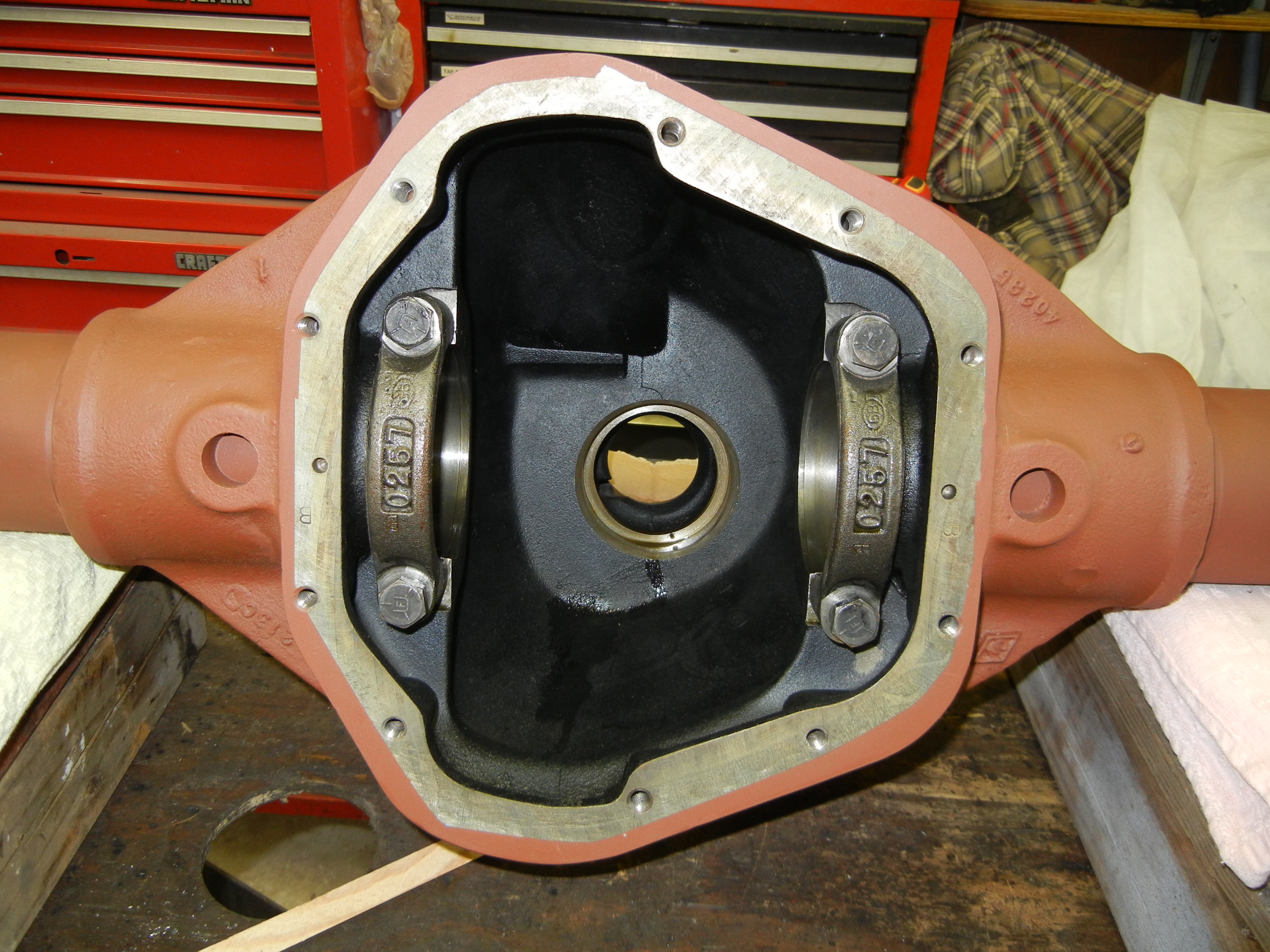
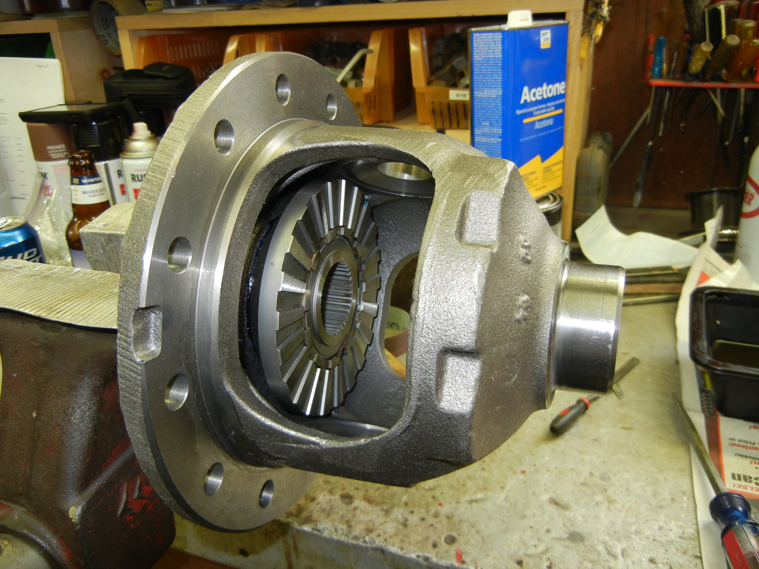
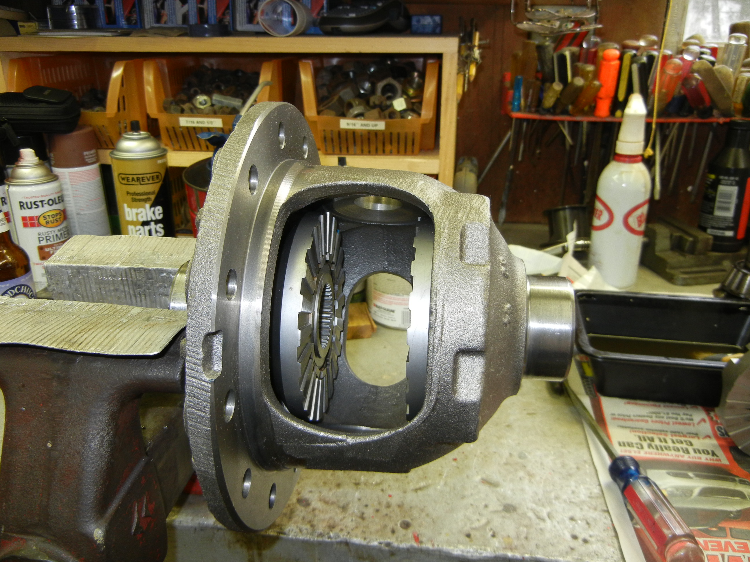
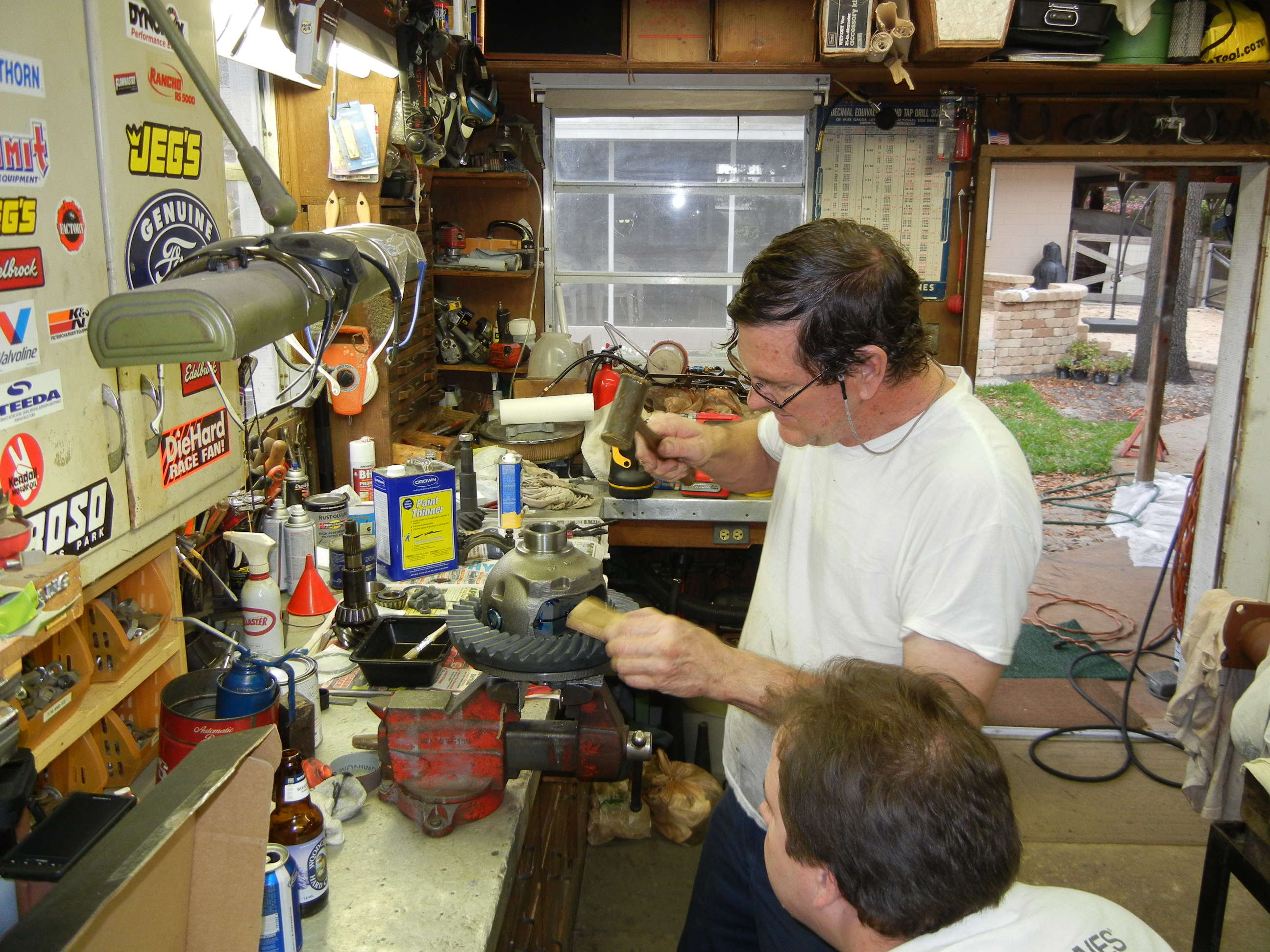
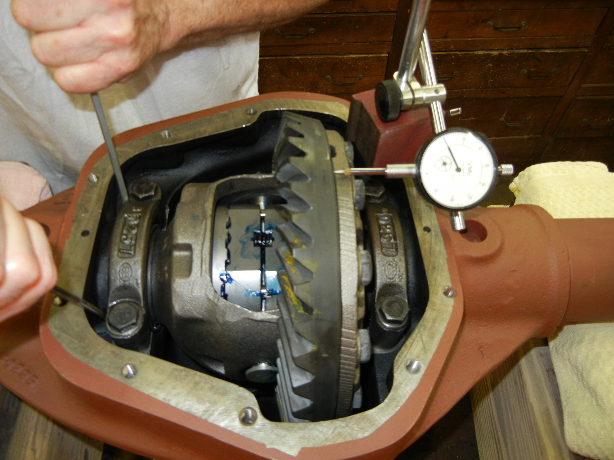
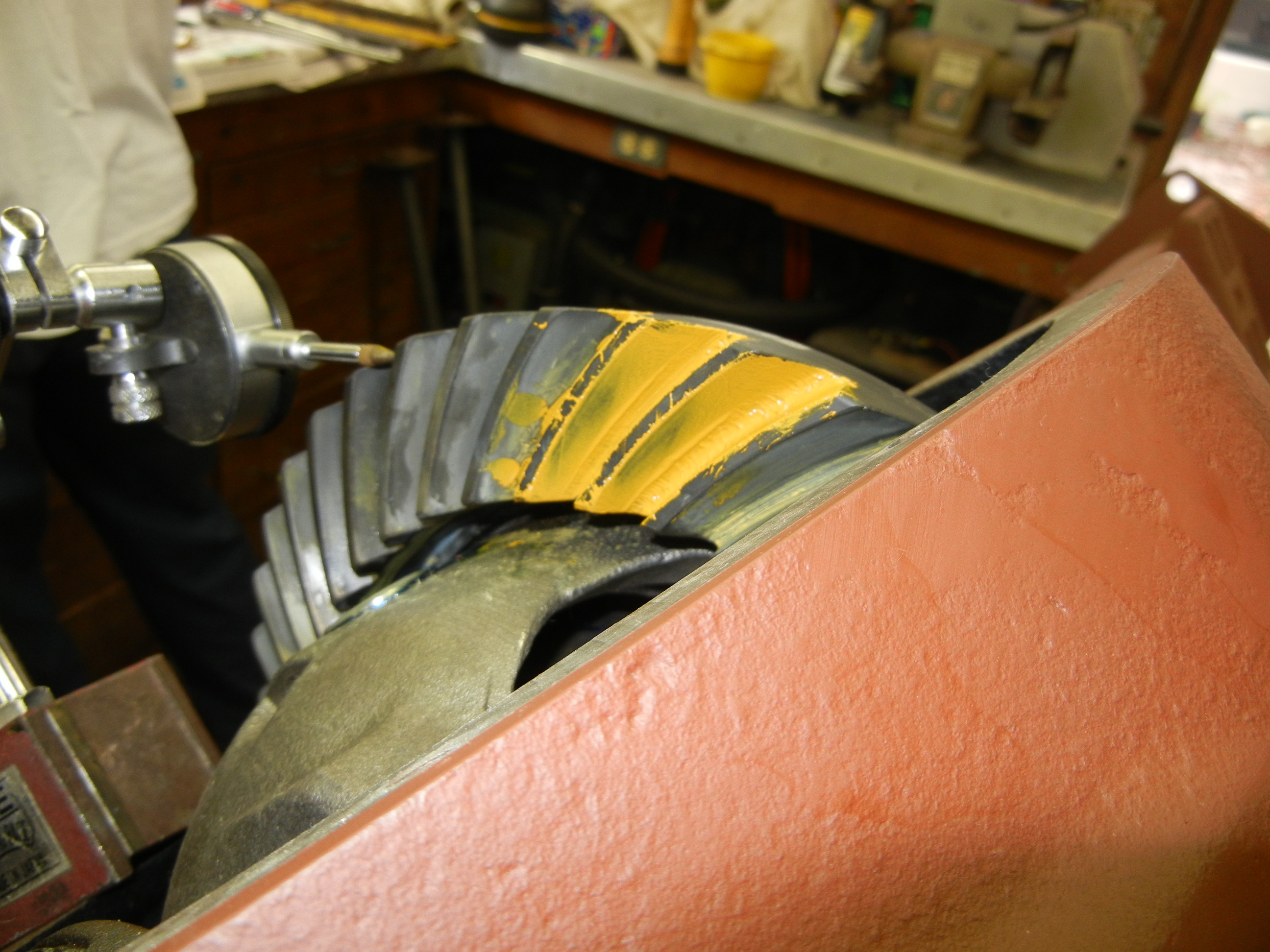
Now it was finally time to start the long trial and error process of
installing and removing the R&P. Before a contact pattern could even be checked,
first the carrier side play had to be determined, second the pinion preload had
to be achieved, third the carrier reinstalled and backlash checked and finally
fourth the contact pattern was checked. We made four contact pattern checks each
with many of the above steps performed in between to get the preload and
backlash set correctly (carrier end play was only checked the first time). There
are many resources on the web to help assist with gear set ups. You will also
find conflicting results of what is considered an "acceptable" contact pattern.
I won't go into detail here but will say our Ford 1978 shop manual was the prime
information resource.
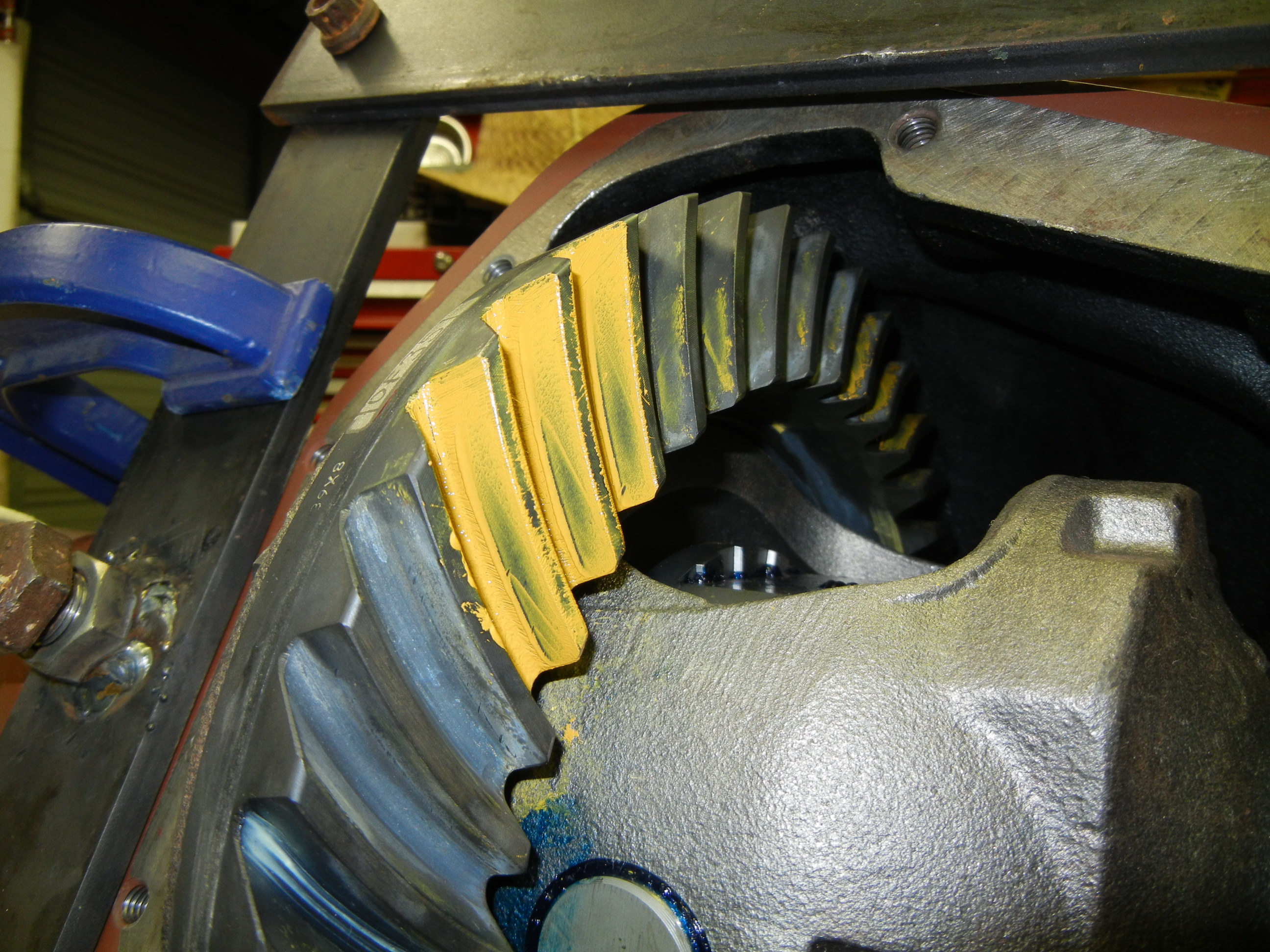
First check-
this was "rushed" as we just wanted to check the first contact pattern. The
backlash was way too much and we were not dead certain of the carrier end play.
So this was just a mock trial to see how far out of spec we were. Surprisingly
the pattern wasnt too bad, but again needed more dialing in.
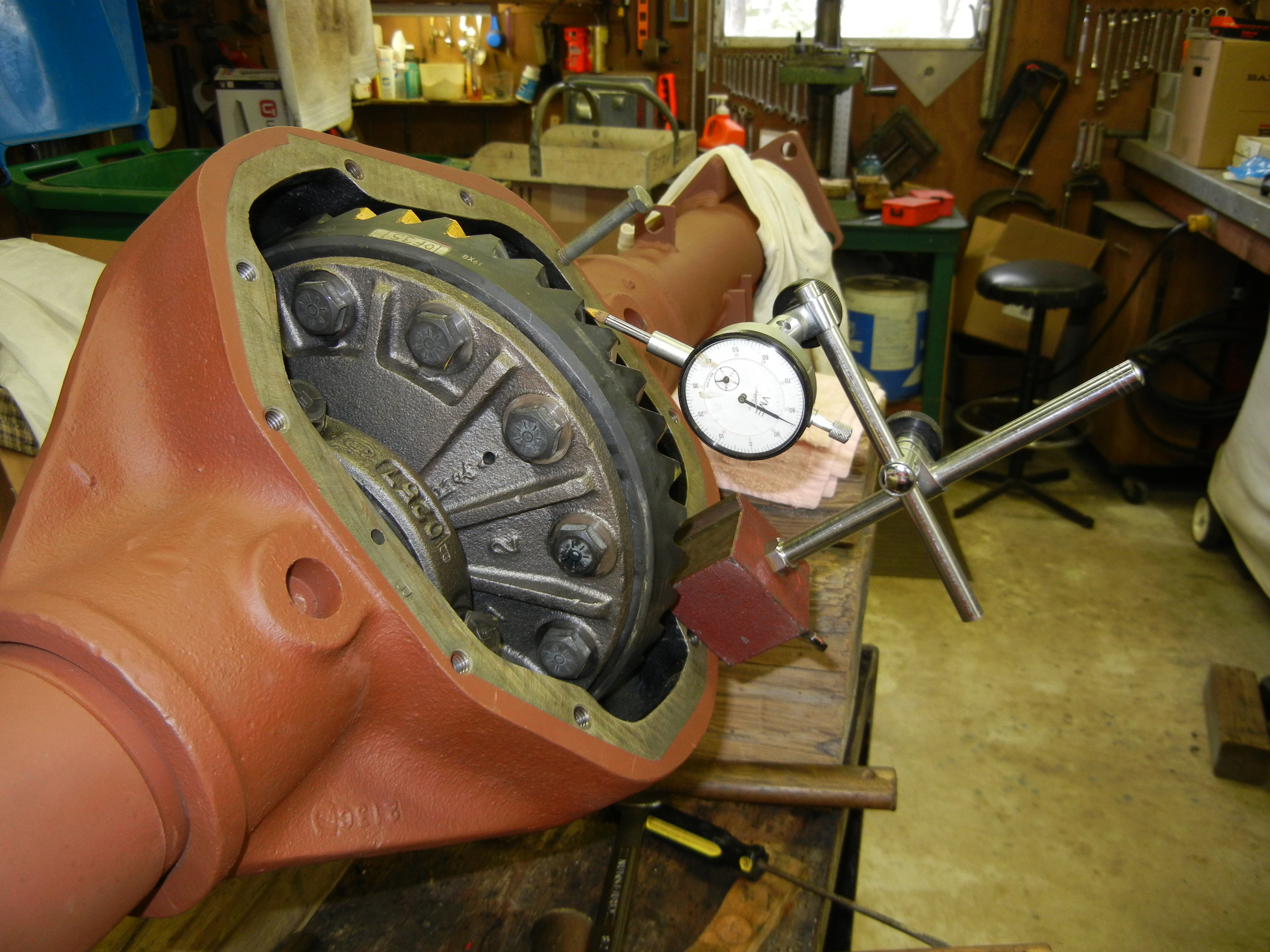
The next day, more care was given to the "proper" set up procedure. We then
figured out the carrier end play and added shims accordingly to get the
recommended carrier bearing preload. A case spreader was used otherwise this
would be almost impossible.
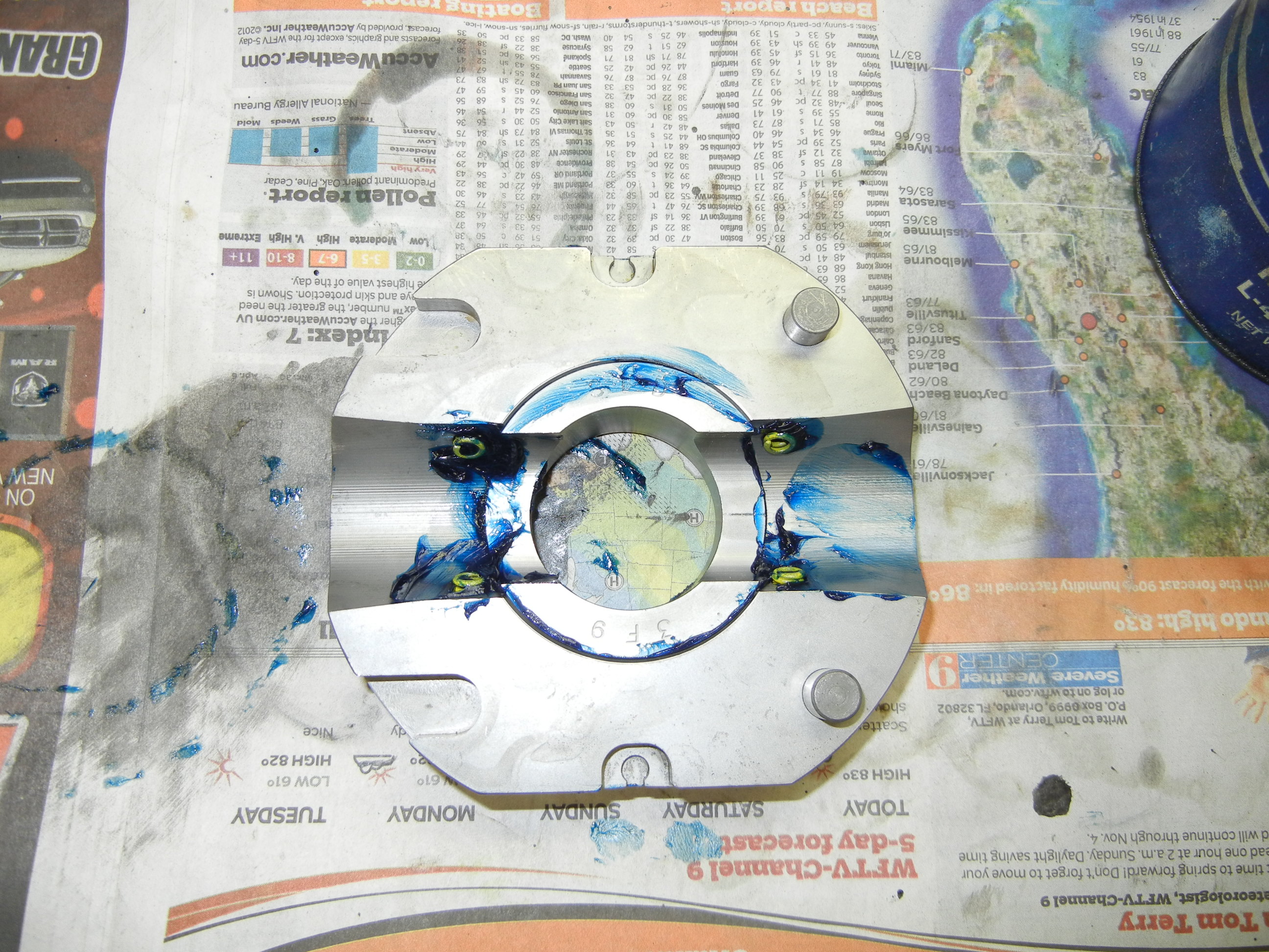
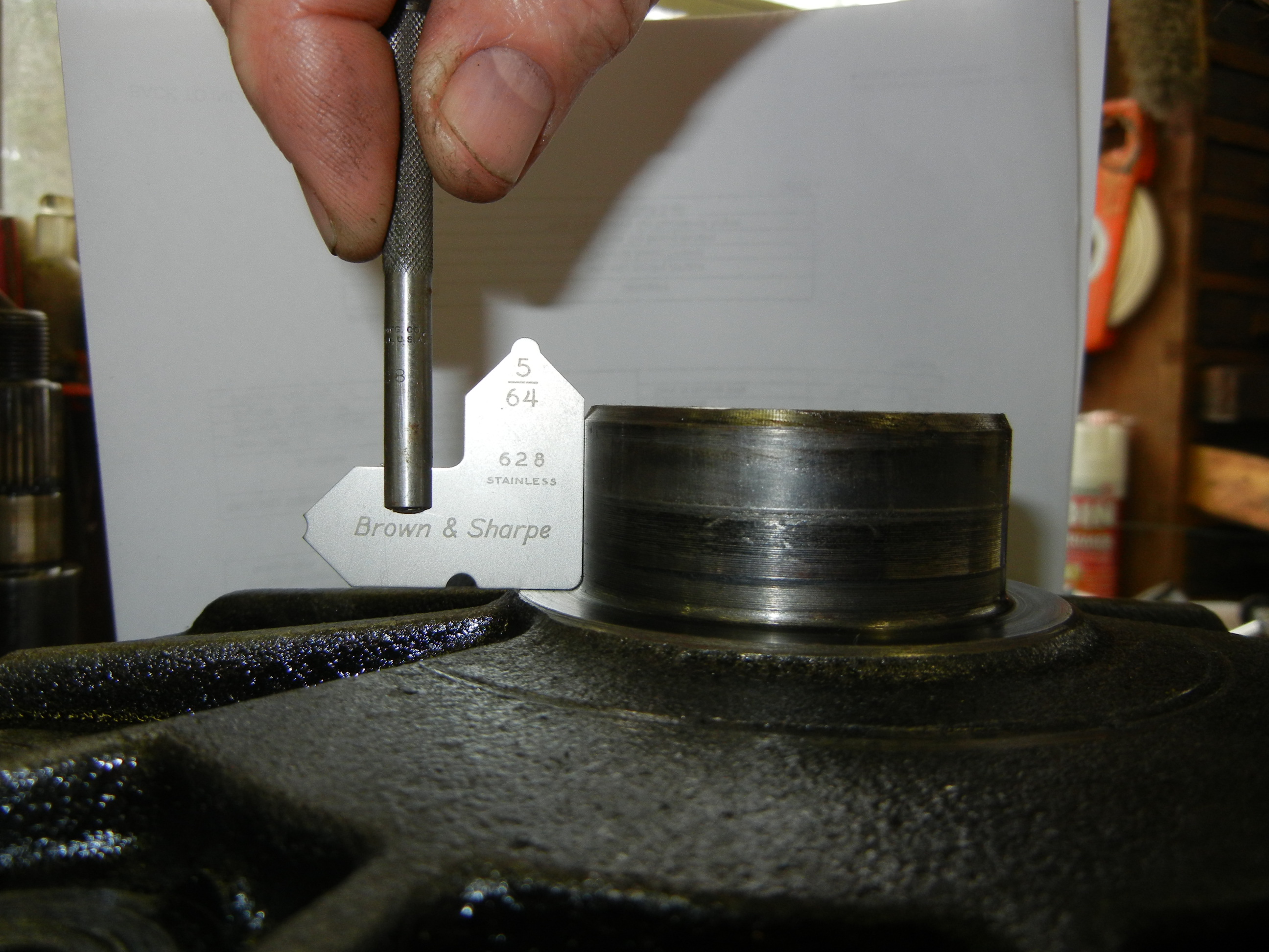
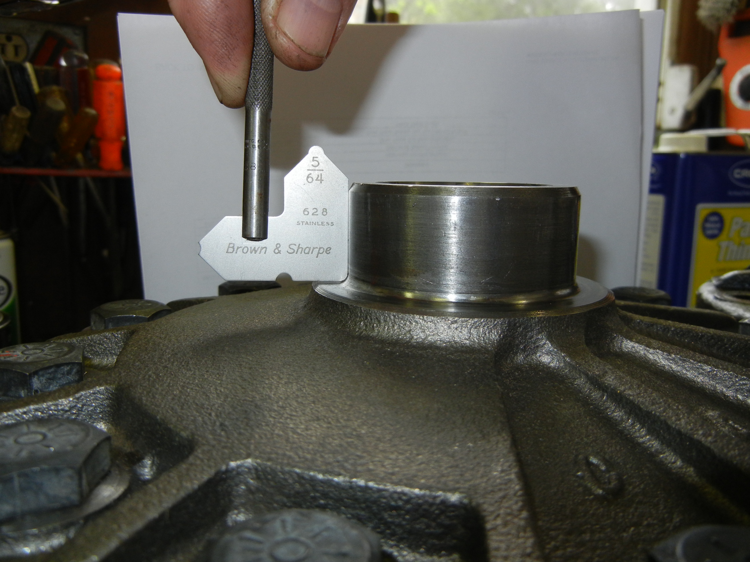
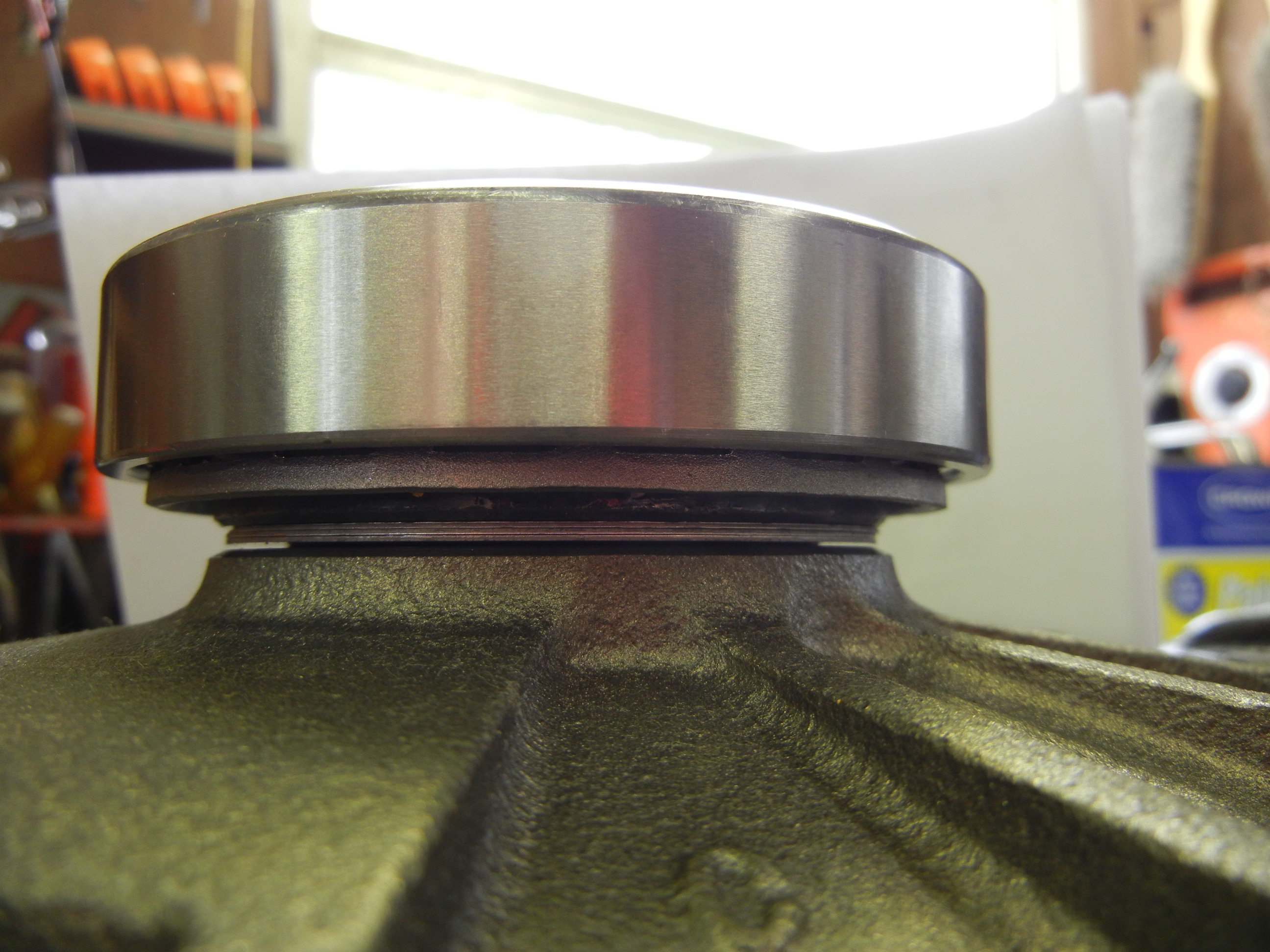
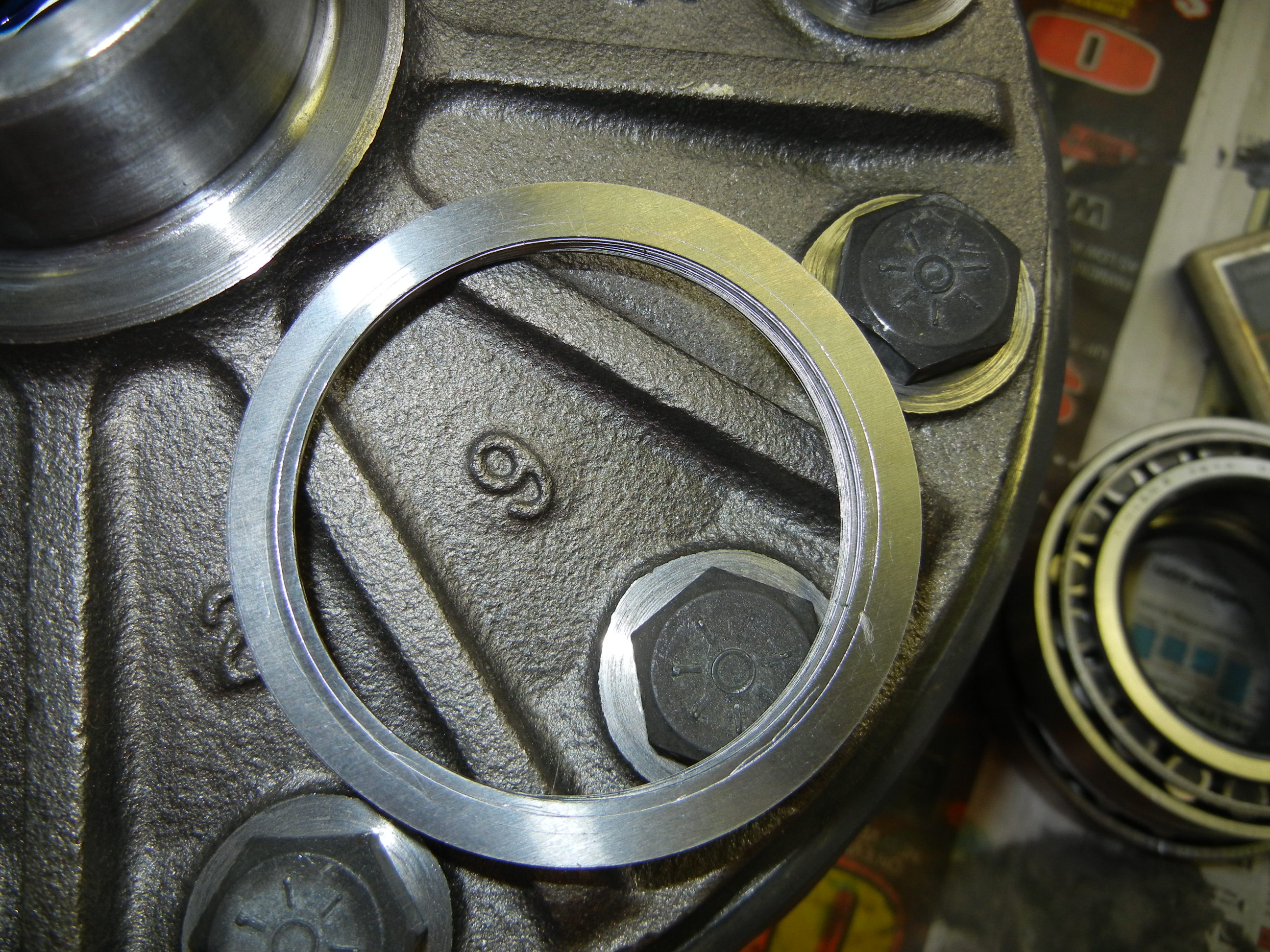
Once the carrier shims were determined, we ran into a huge set back. The
carrier I bought off eBay had a huge flaw in the way of different carrier
bearing shoulder radii. This is a genuine Dana/Spicer carrier so I wonder how
this left the factory!? Basically we had to grind out the inner diameter of the
shims and then chamfer the edges so there would be no buildup of metal to throw
off the thickness. All in all this cost us 2 hours of tedious work that was not
needed! You can see the difference between the old carrier and the new carrier.
Also the bearing pic shows the gap between the shims and the carrier shoulder!
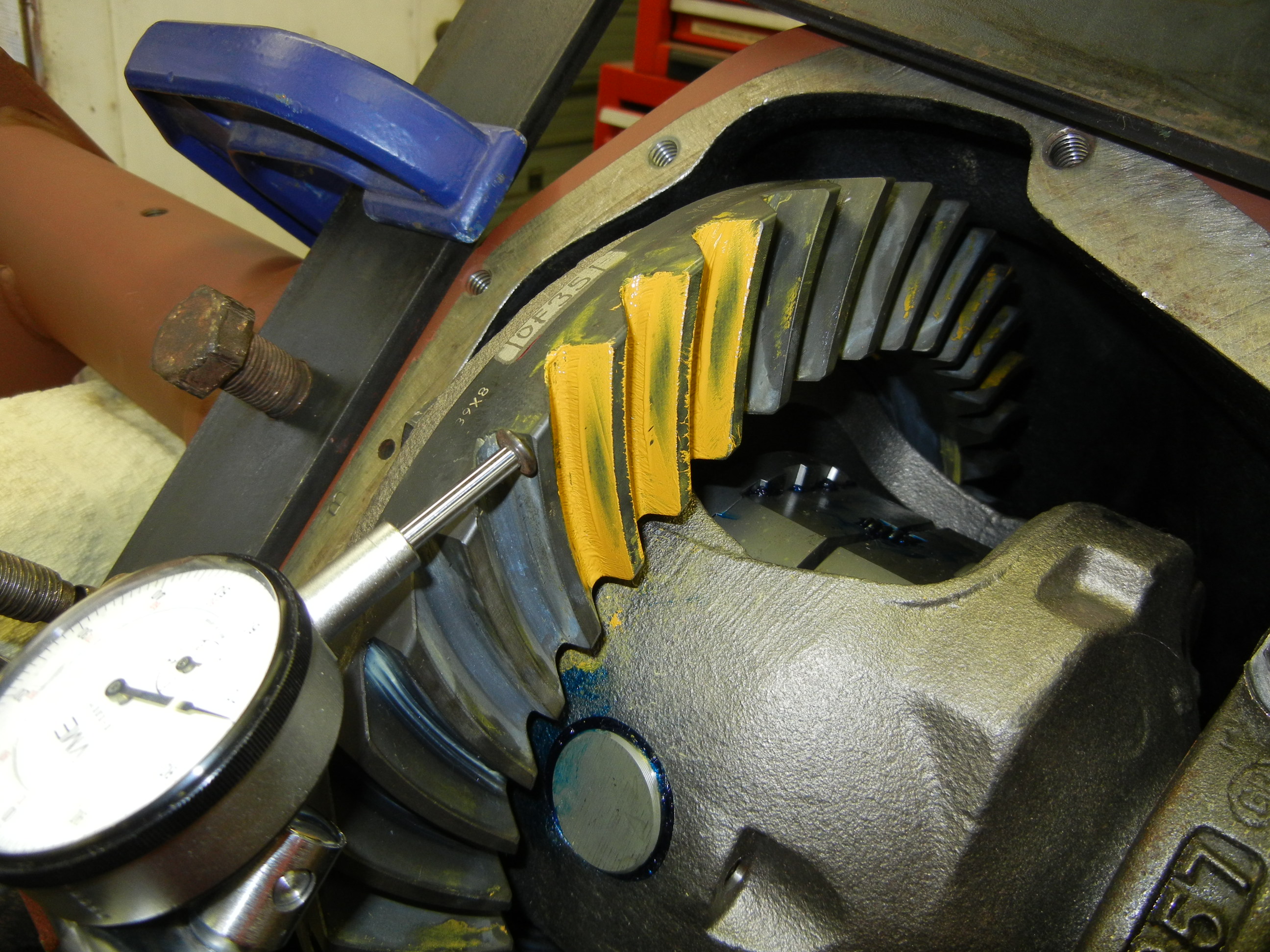
Second check- now with the correct carrier end
play and pinion preload. Pattern looking better but backlash still too sloppy!
Also the pinion is right at the edge of the ring tooth. Pinion depth needs to be
increased or ring gear needs to be moved closer to pinion.
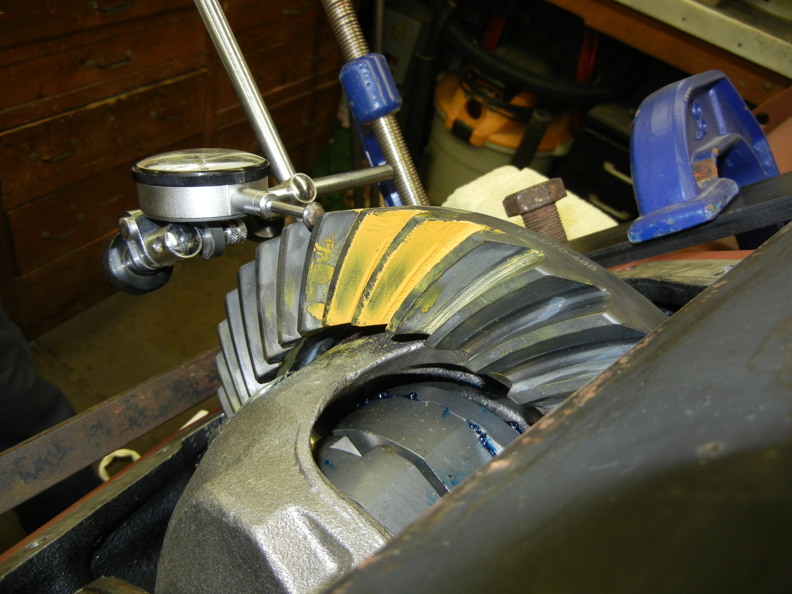
Third check- contact pattern looking even
better, but backlash is still too sloppy. The coast side even looks more
promising!
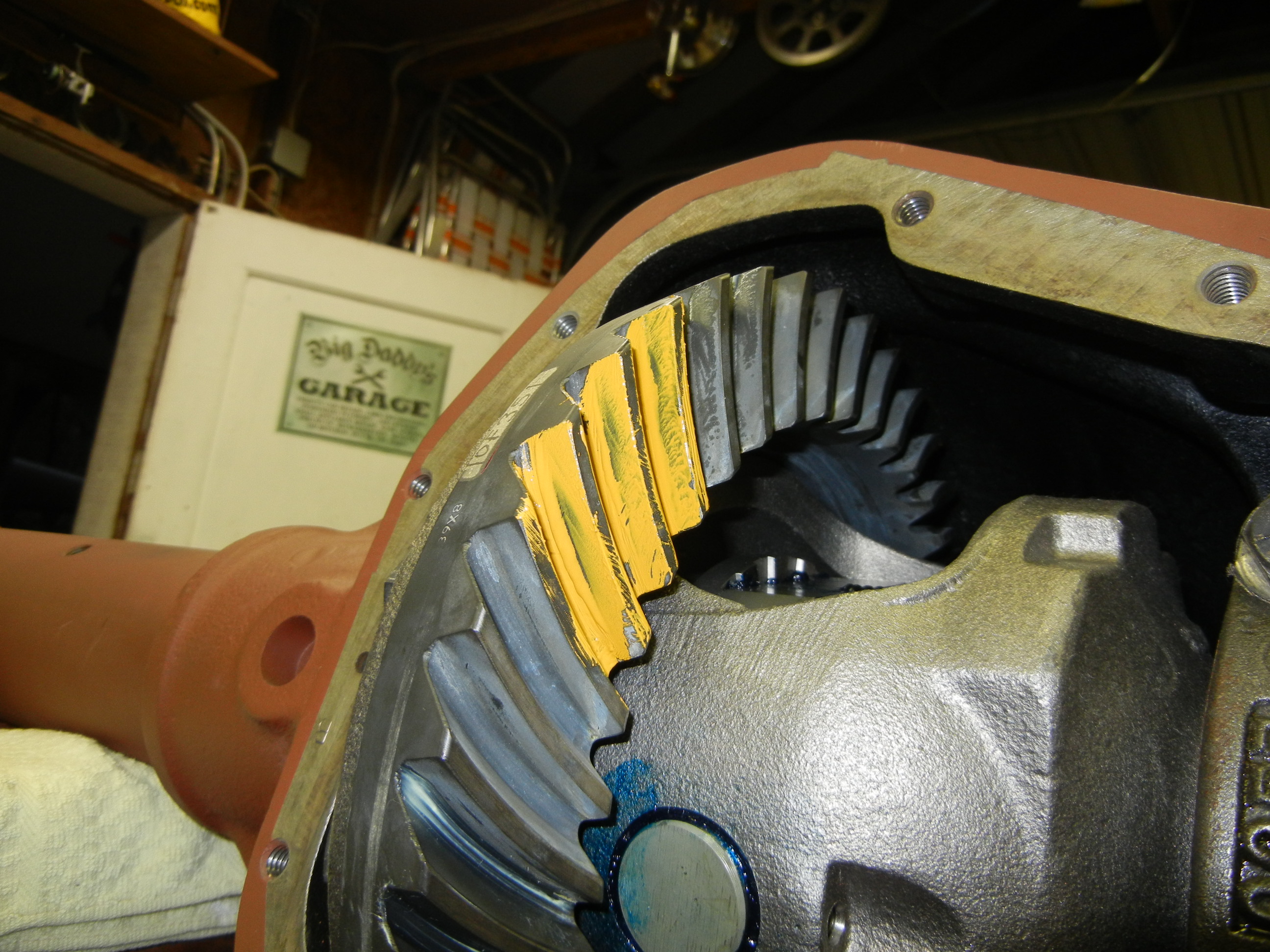
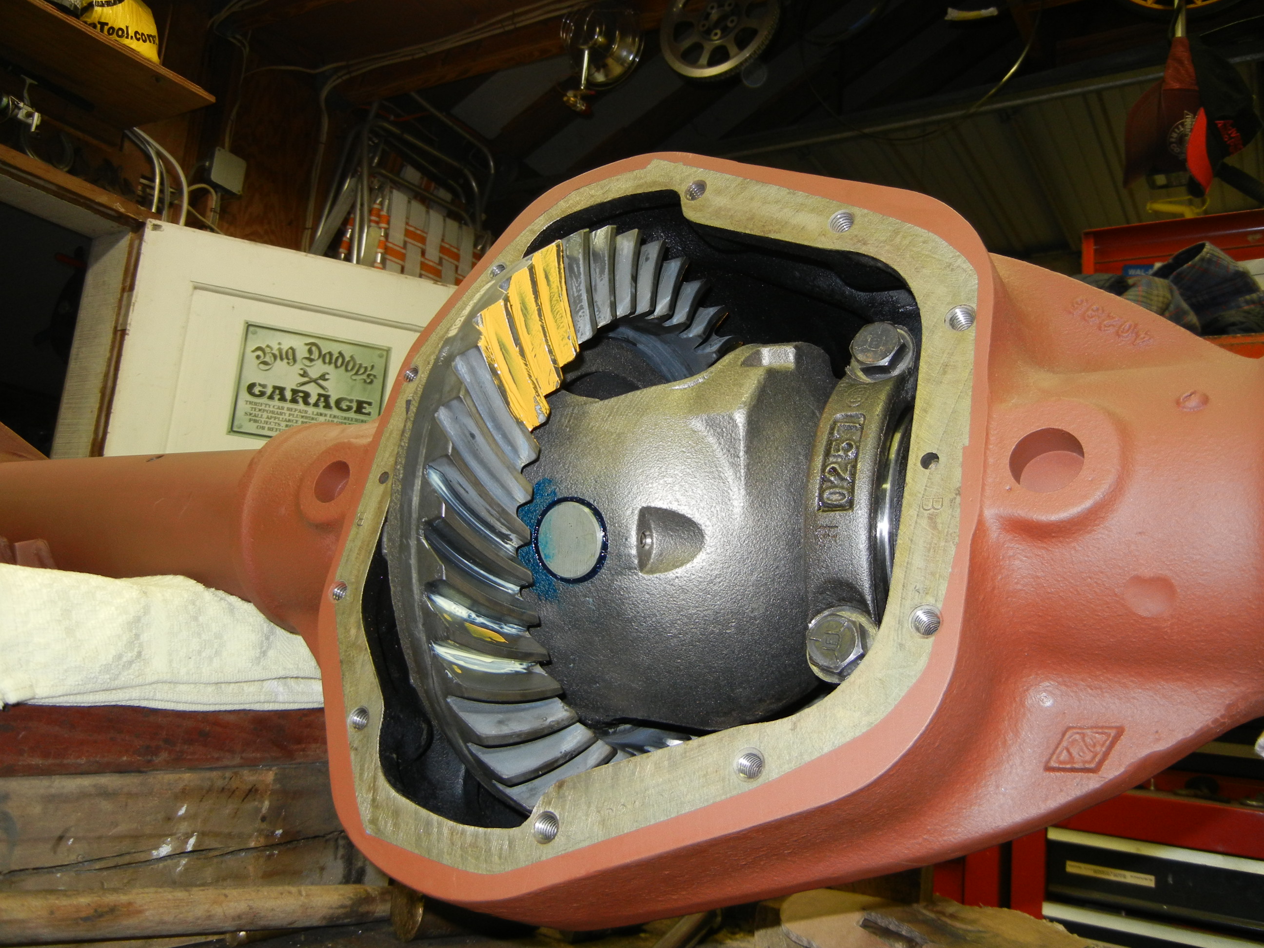
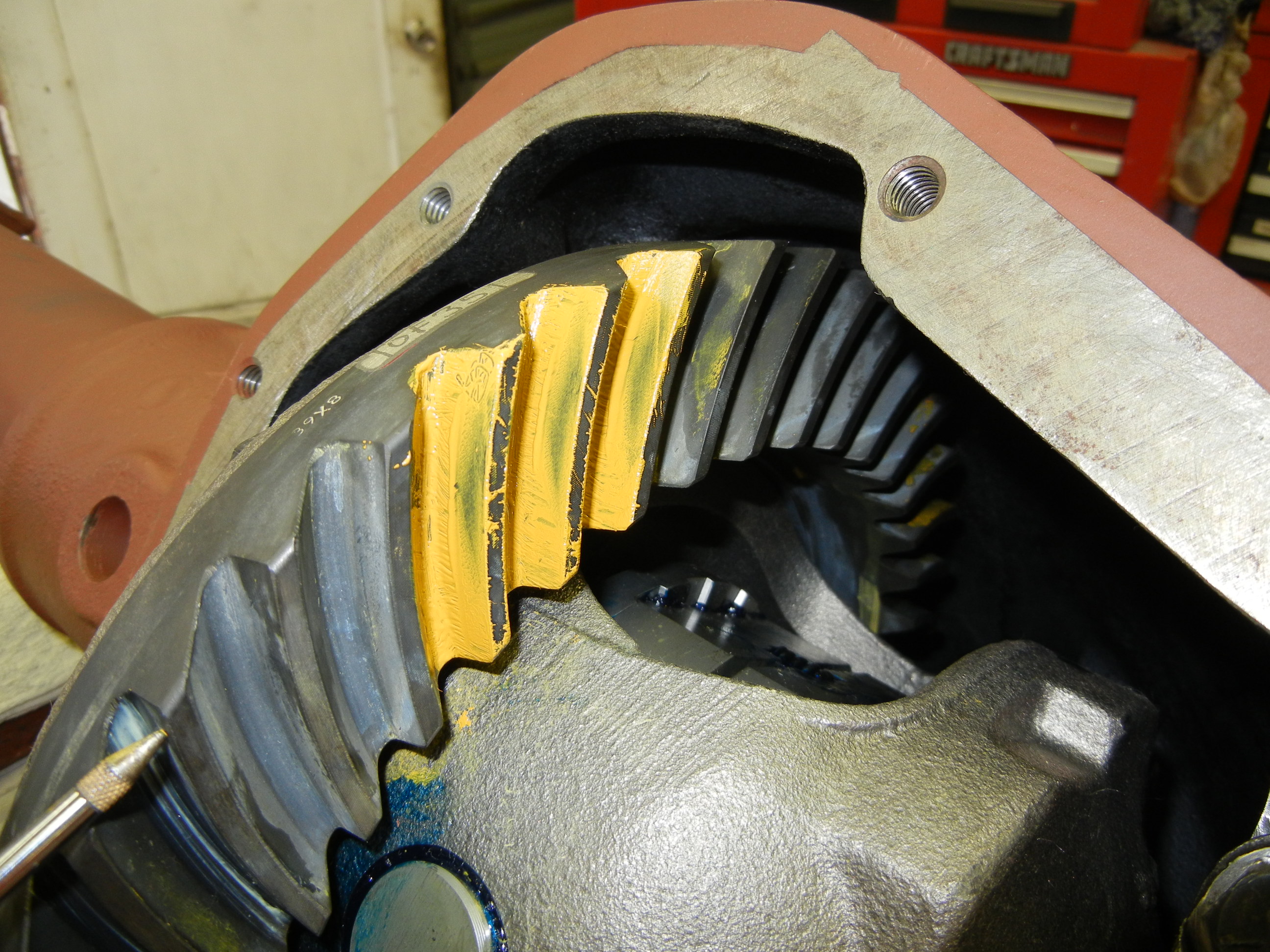
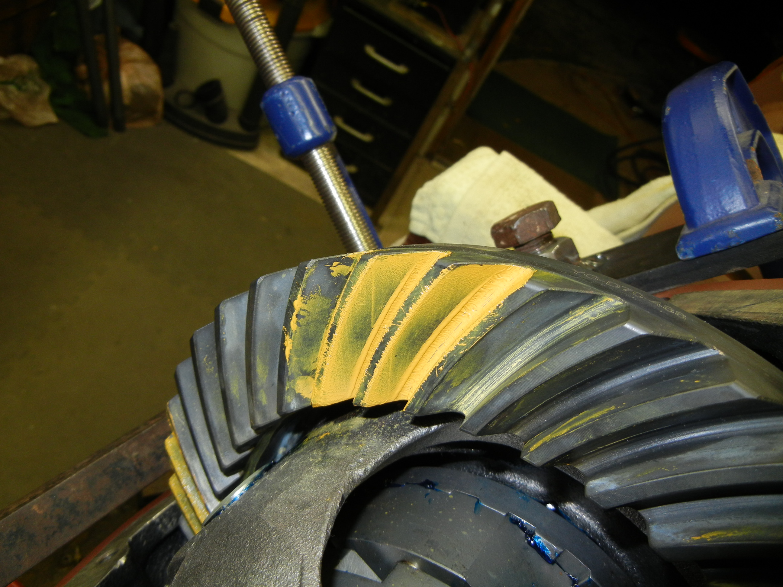
Fourth and final check- the backlash is now dead
on at 0.005" and look at how good the coast side is! The drive side moved
slightly but according to the pattern shown is still acceptable. If you look
closely enough, you will see the marking compound is smeared almost over the
entire drive side of the tooth. According to the mixed reviews, this is know as
the "competition contact" and is suitable as there will be more even contact
once the gears set in. We are very happy with these results and feel it is not
worth trying to make any better.
The next step will be to remove all components and press the new bearings on
with the appropriate shims. After three days of gear set up, about 8-9 hours was
probably spent on the actual set up process. The other time wasters not
accounted for were the carrier shoulder/shim fix and the modification of the
case spreader to work on the D70 (was previously built for GM 10/12 bolt axles).
Very rewarding versus the local driveline shop's labor quote they gave me!
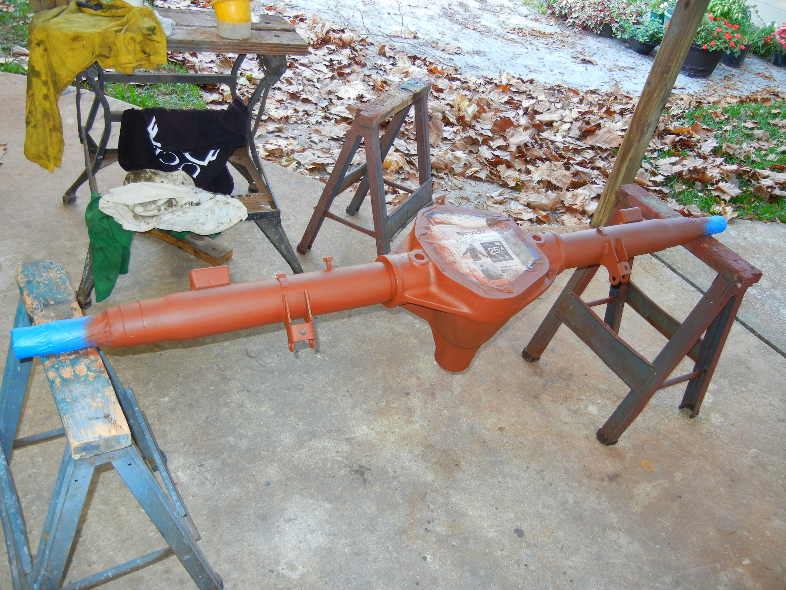
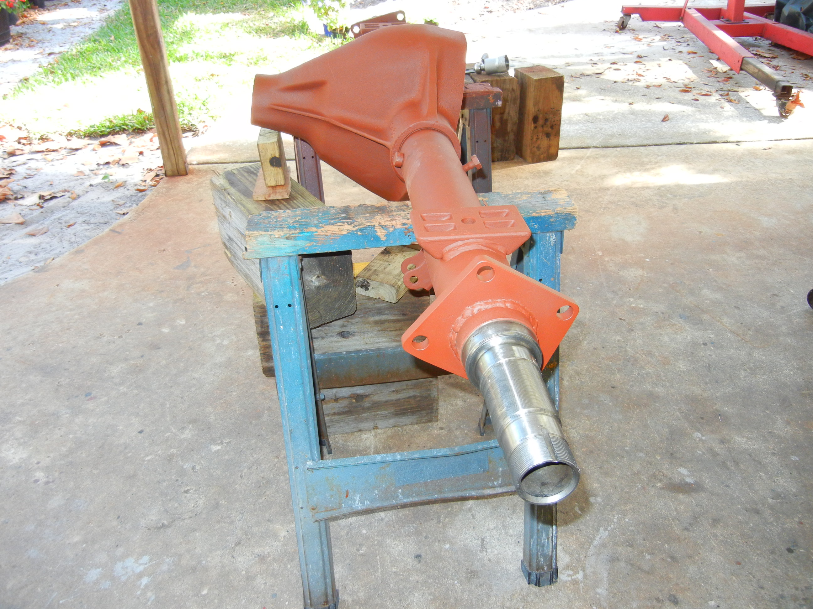
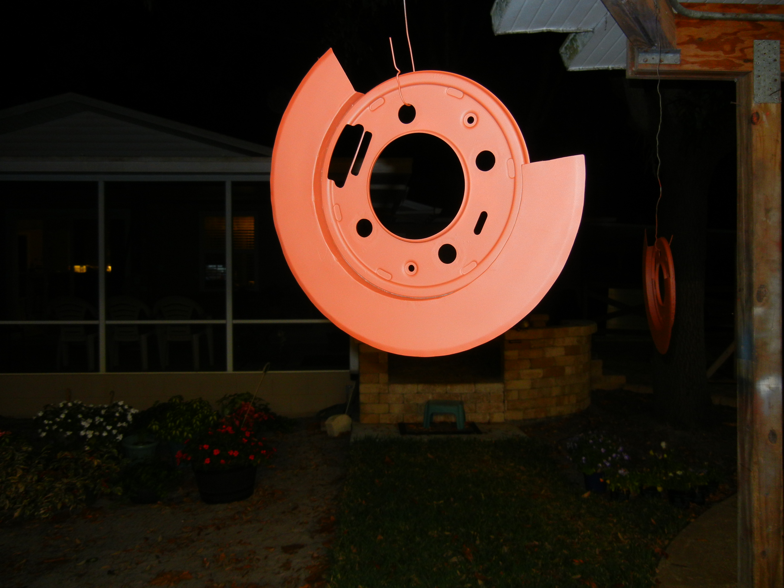
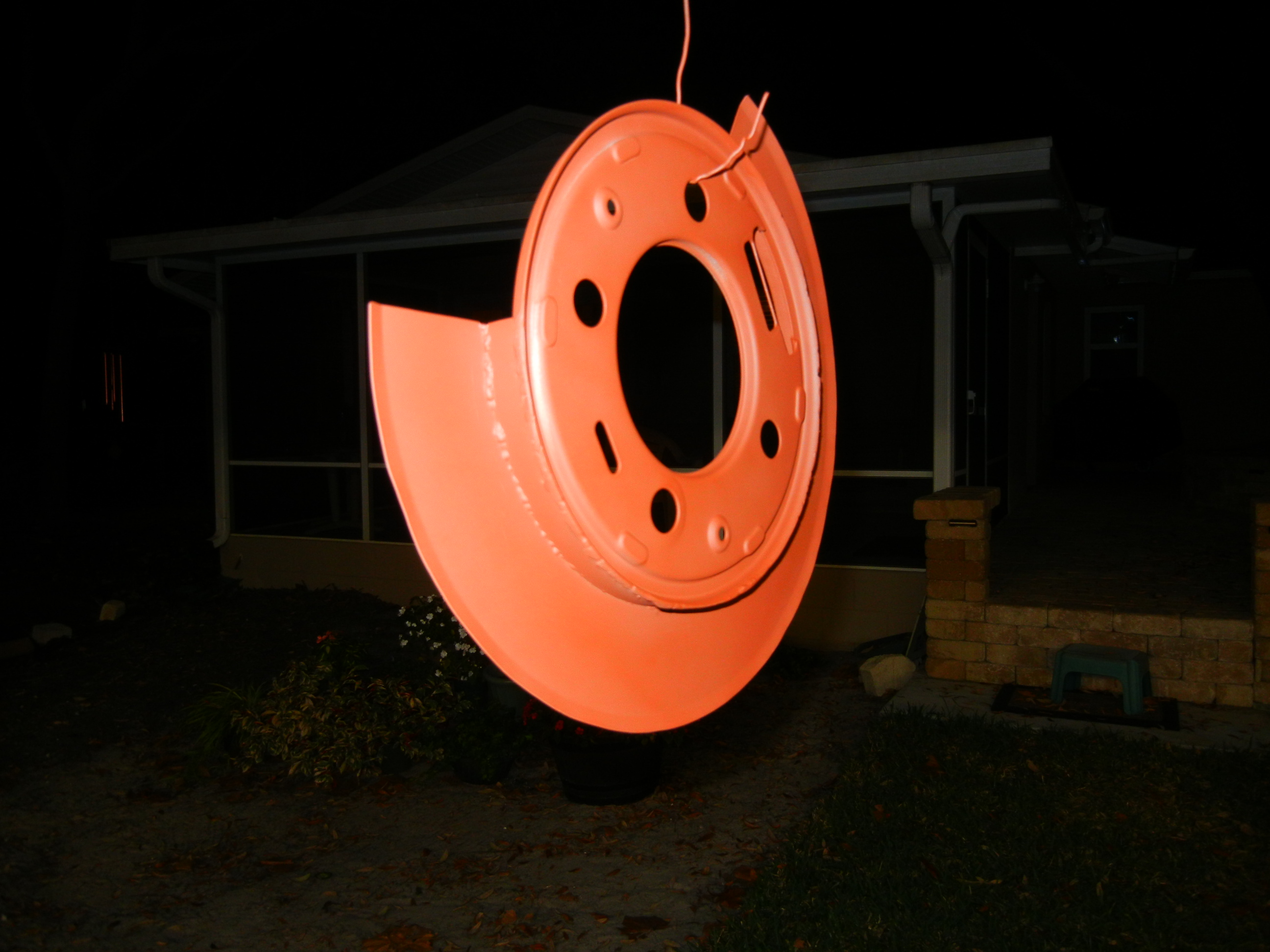
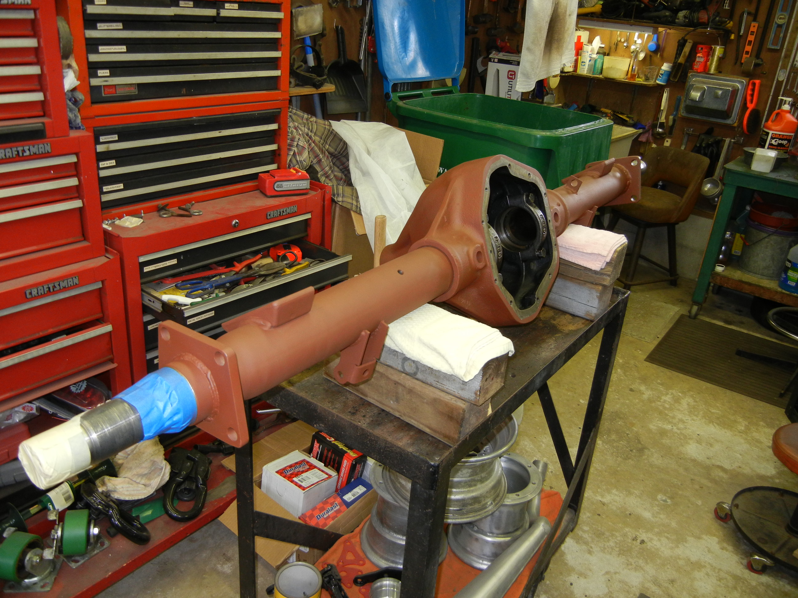
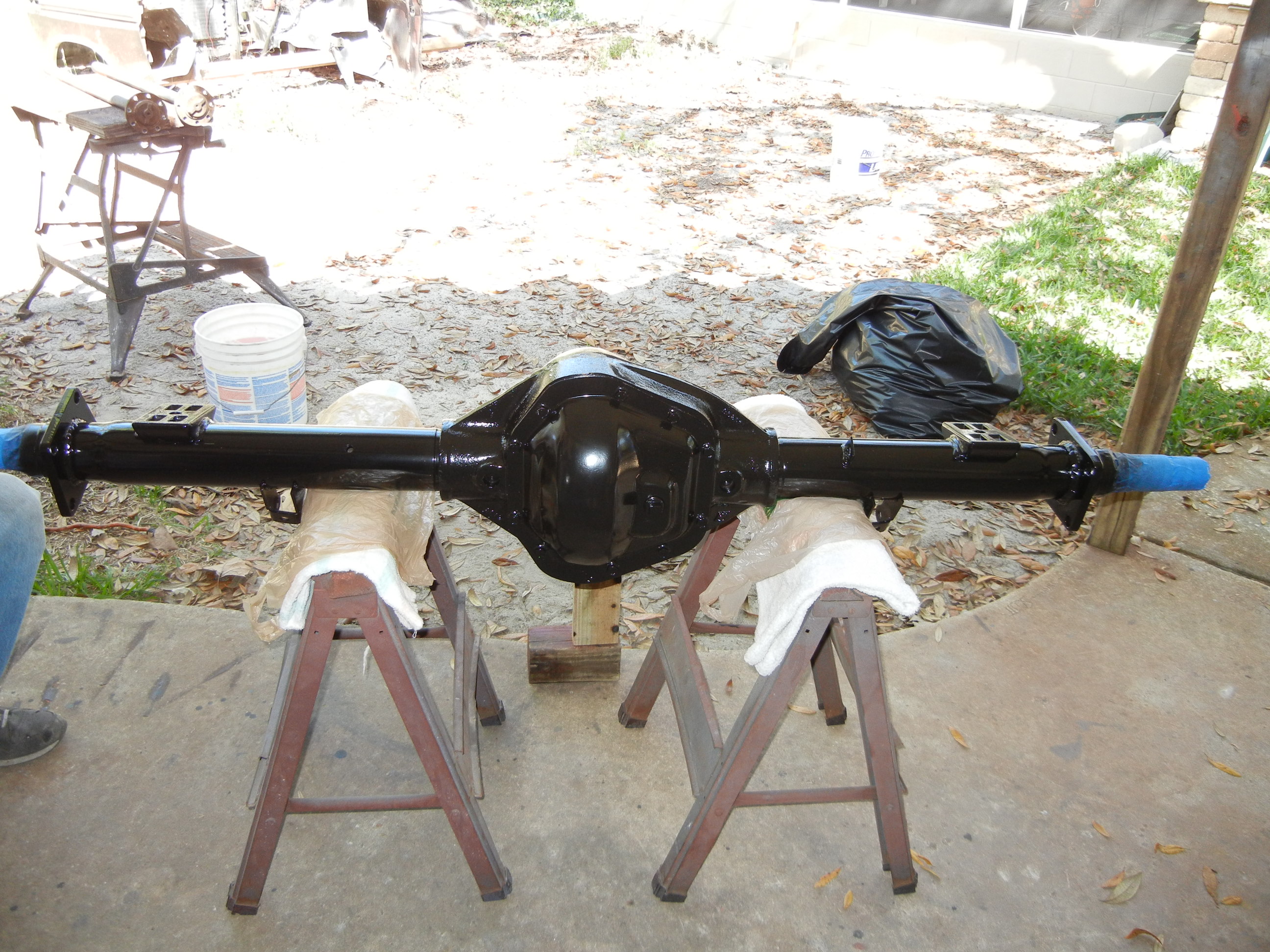
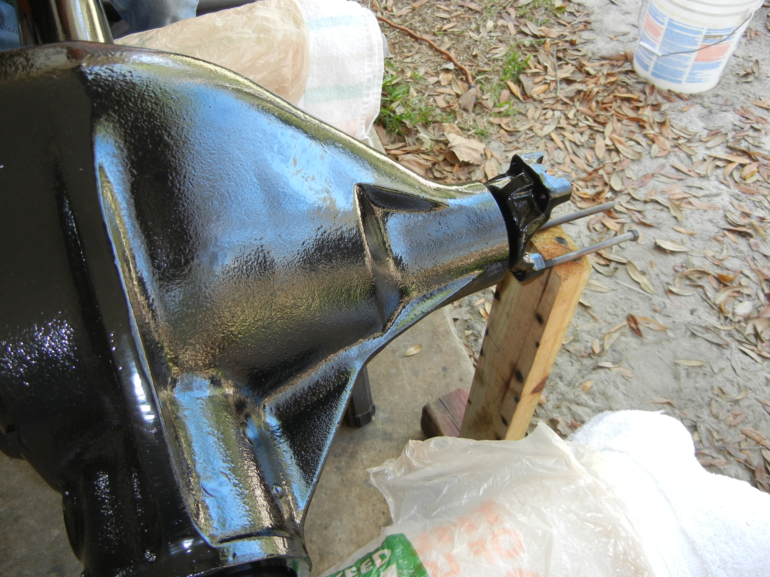
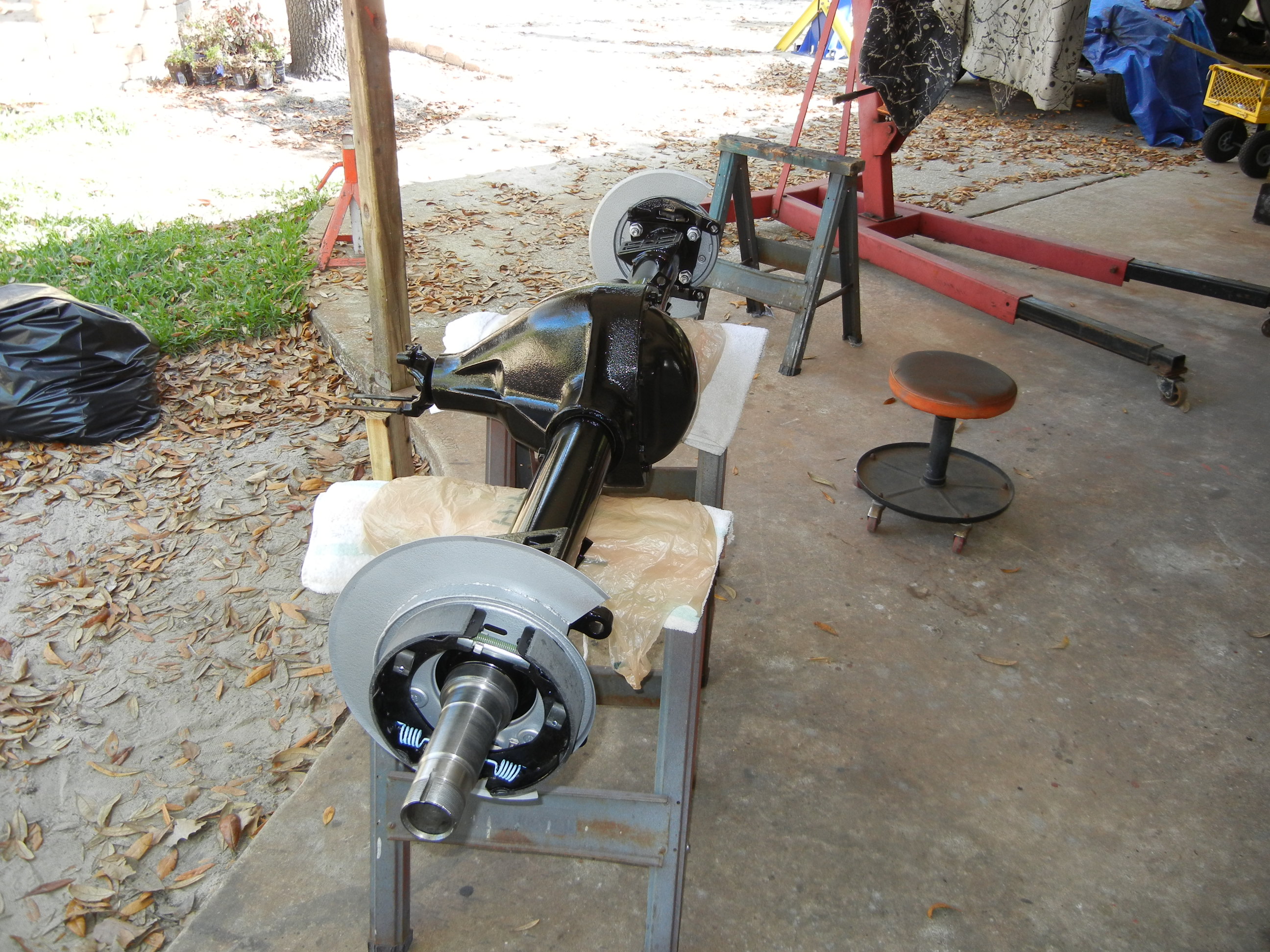
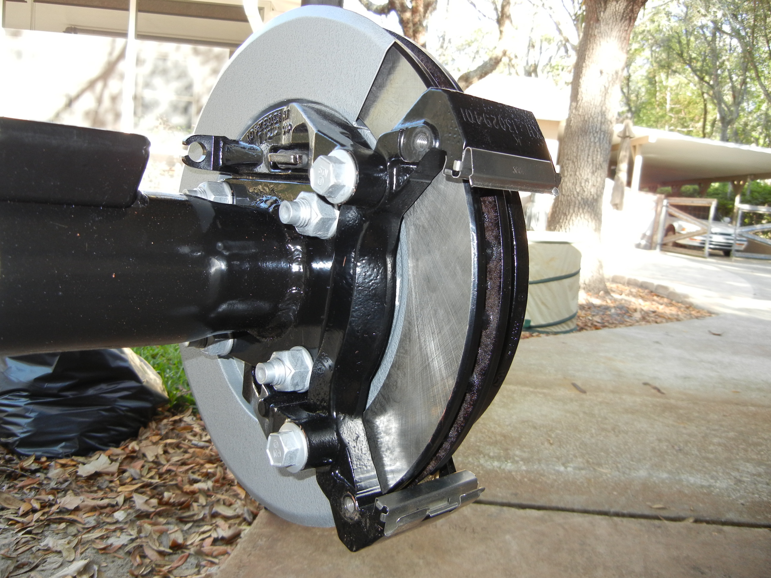
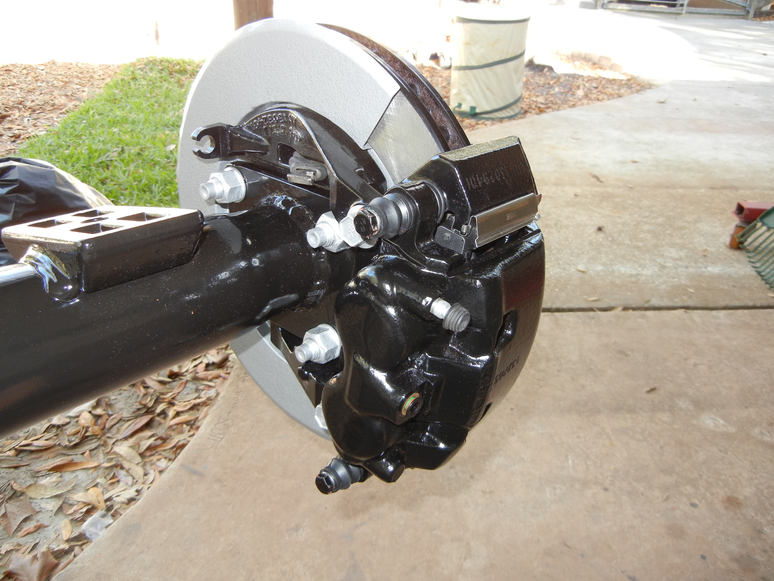
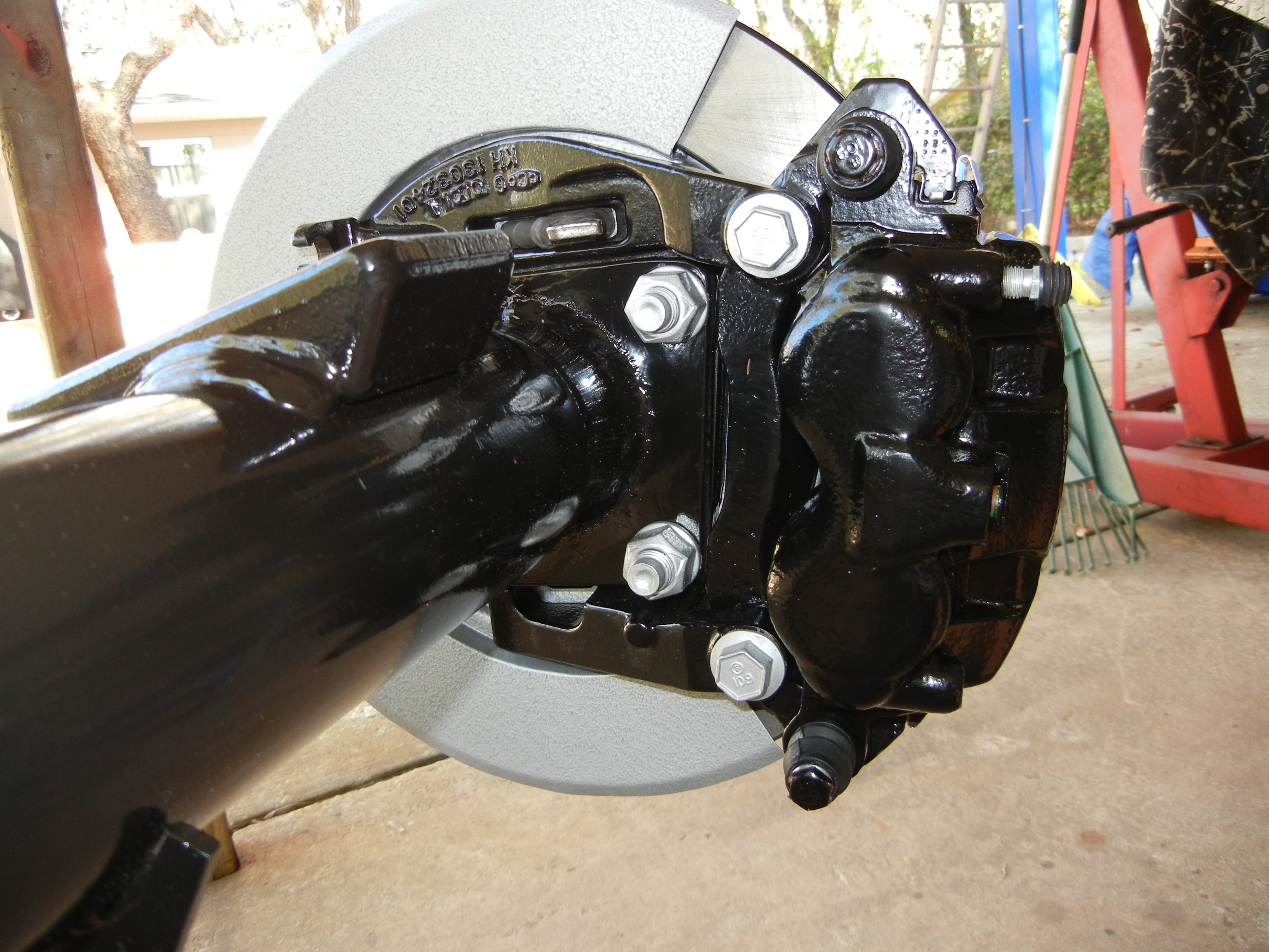
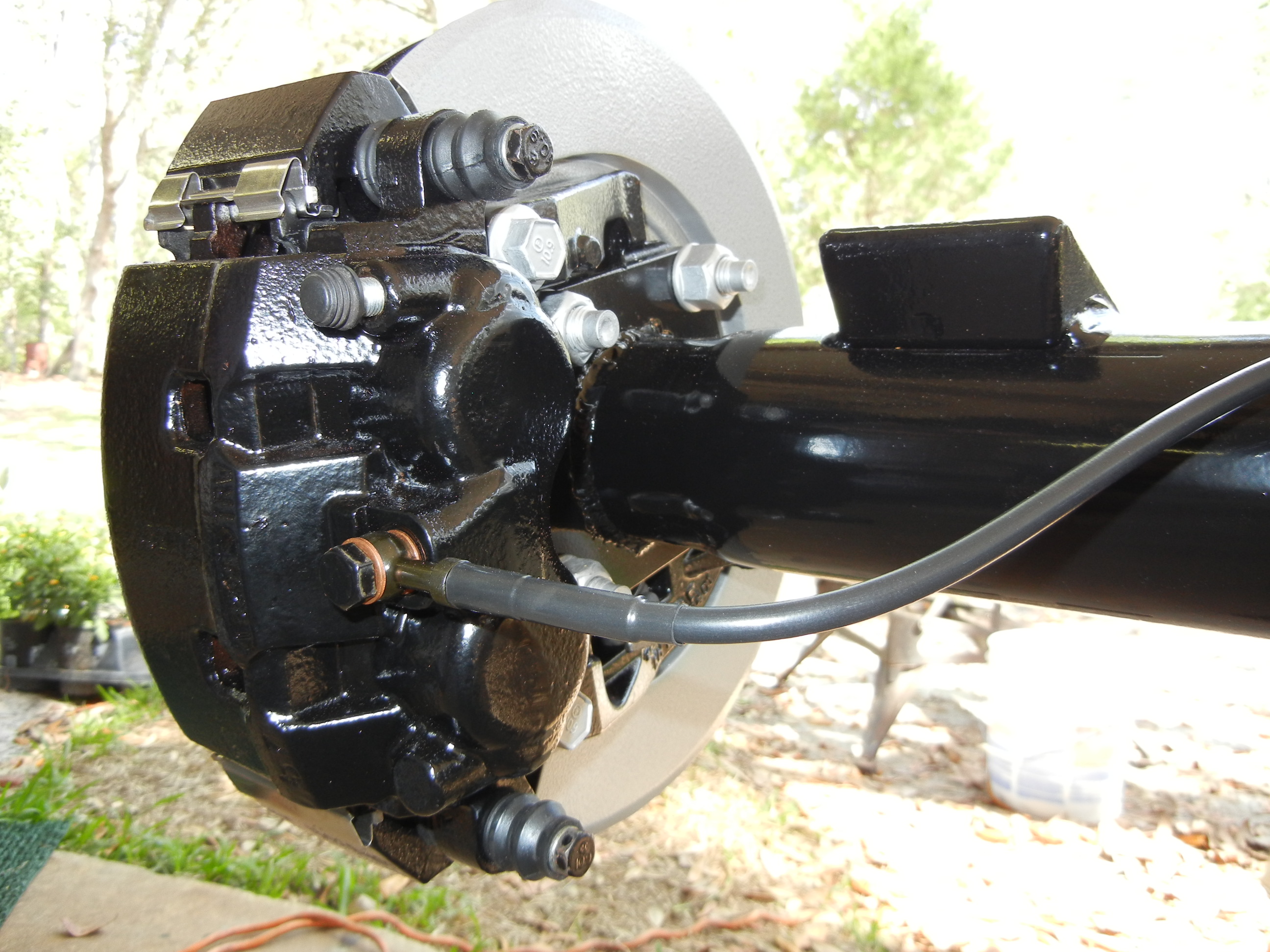
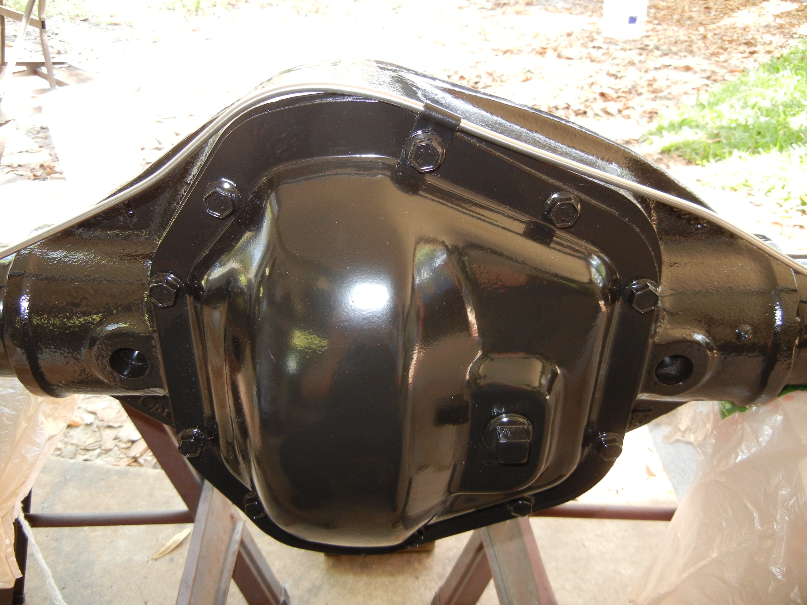
Once the gear setup was finished, gloss black paint was used to protect the
axle from any further elements. All brake brackets and other components were
torqued to spec.
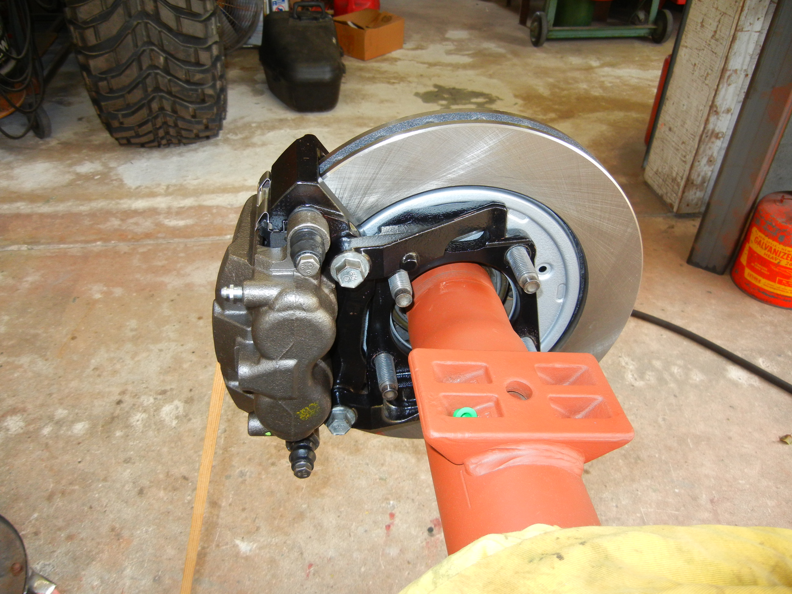
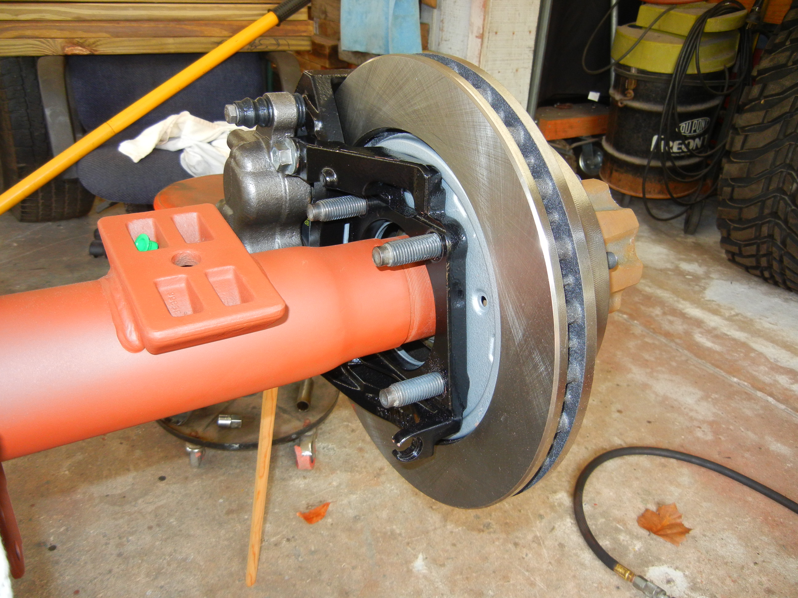
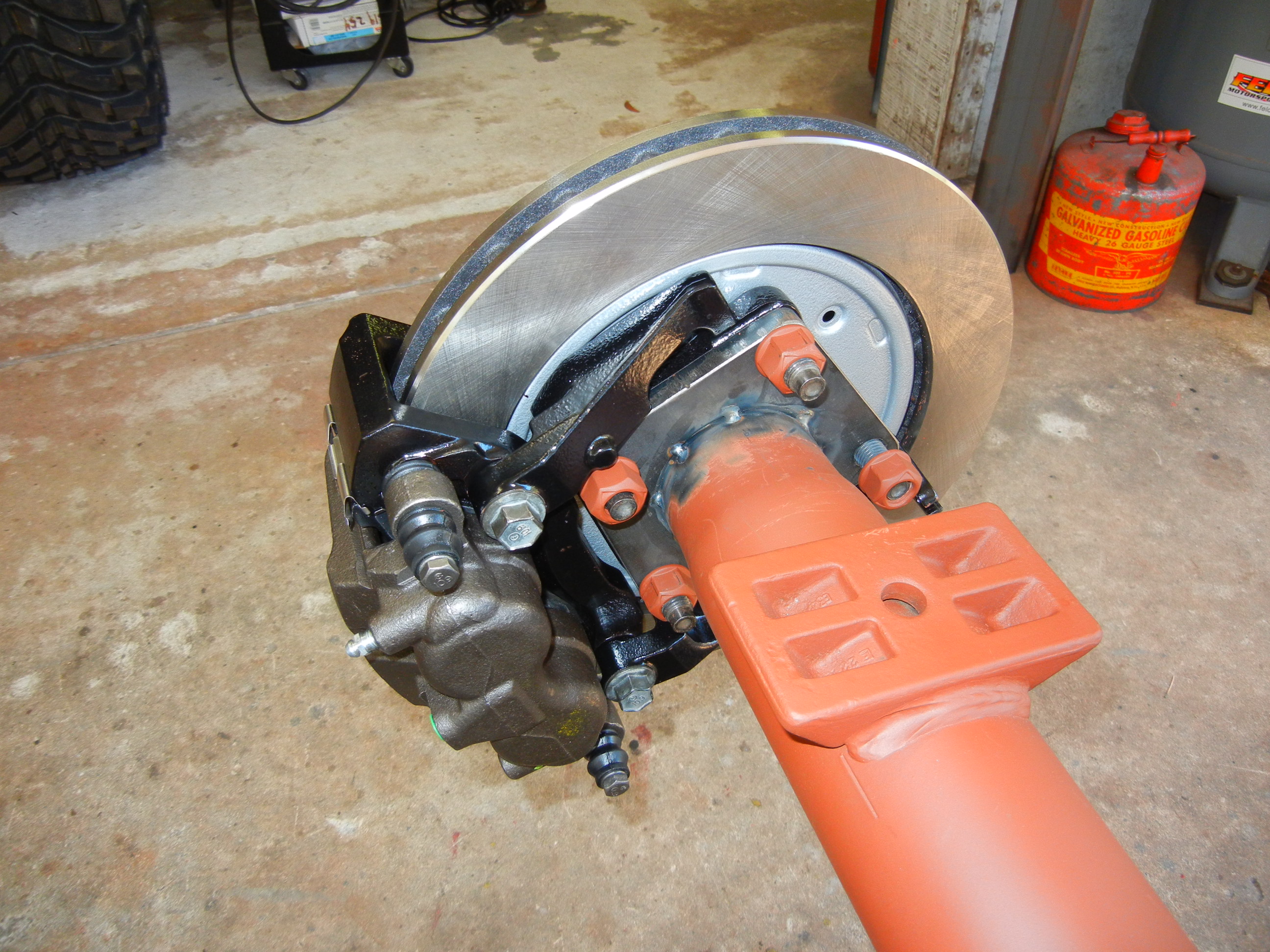
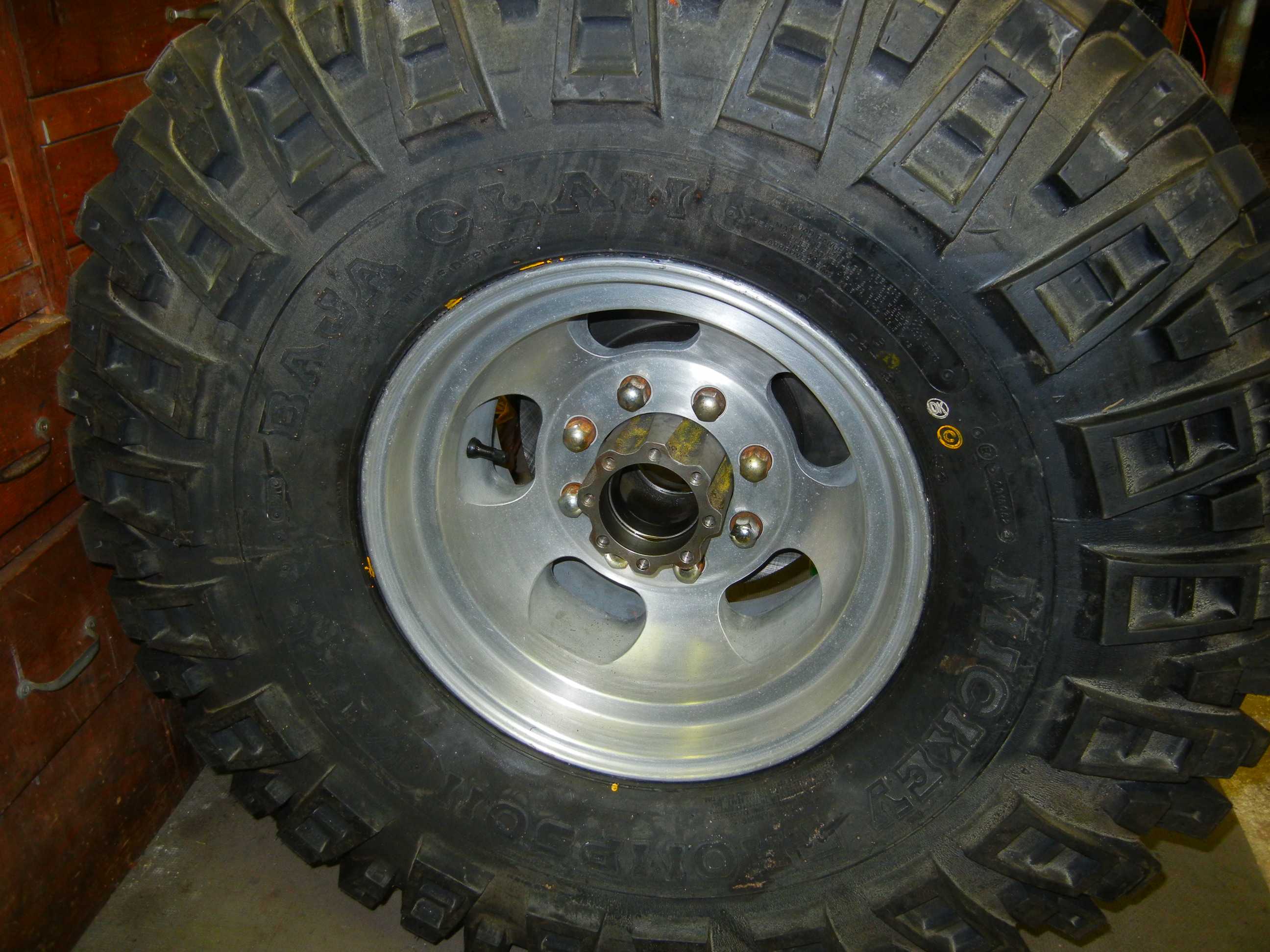
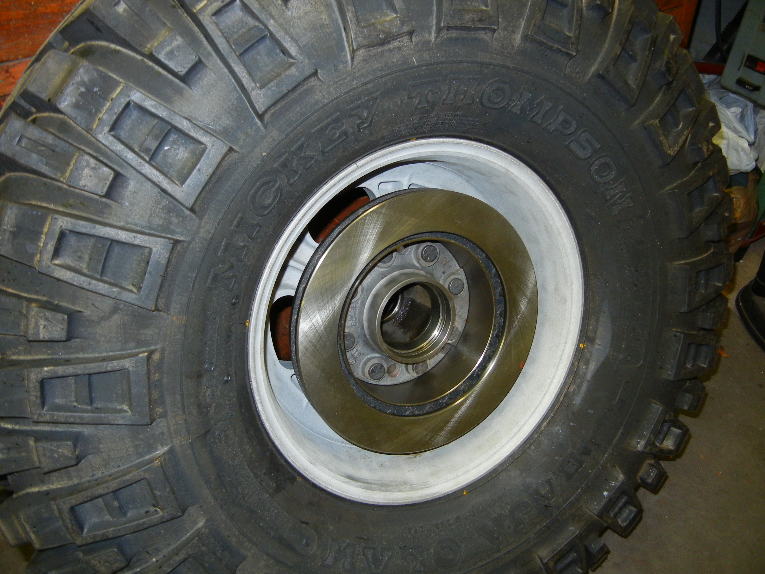
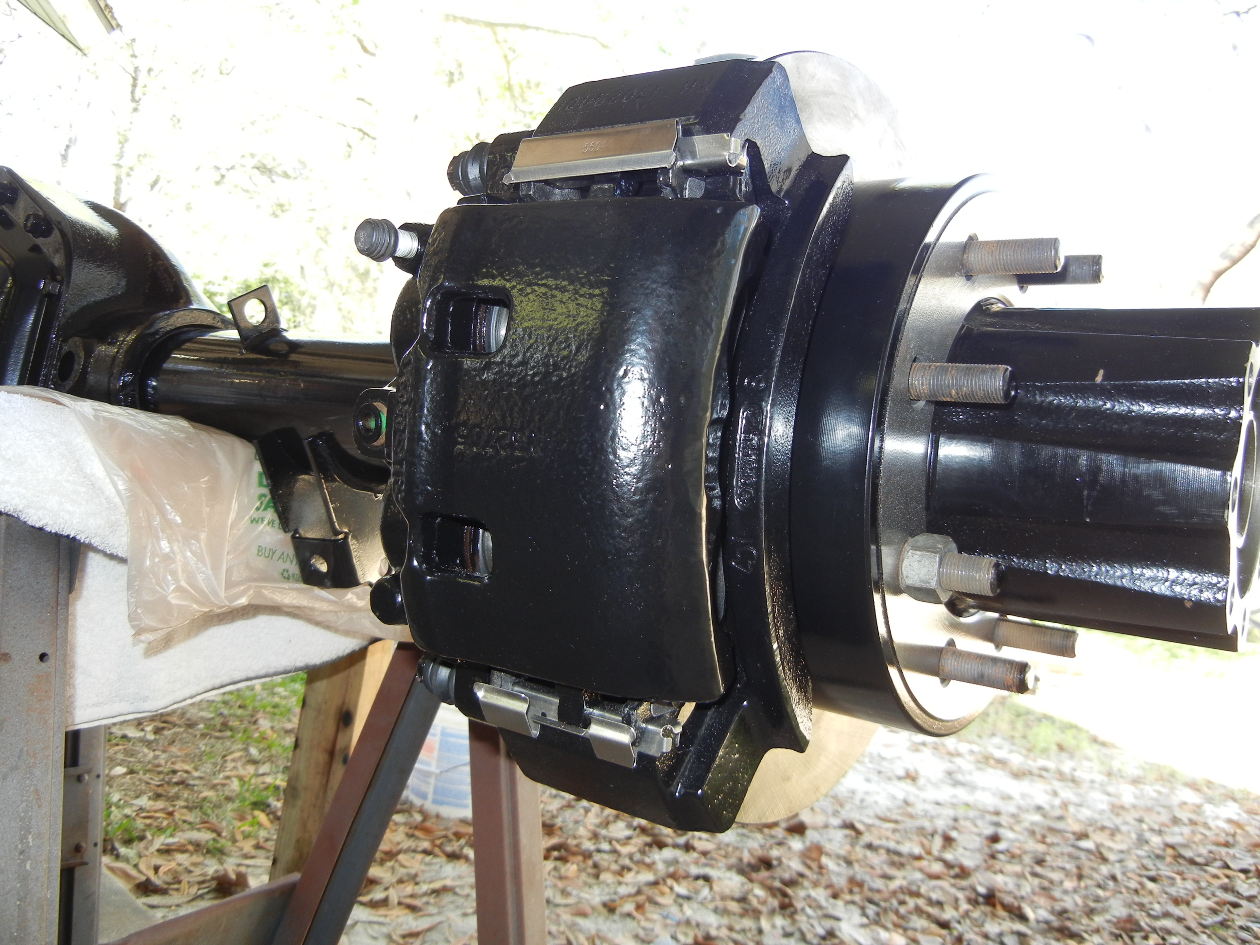
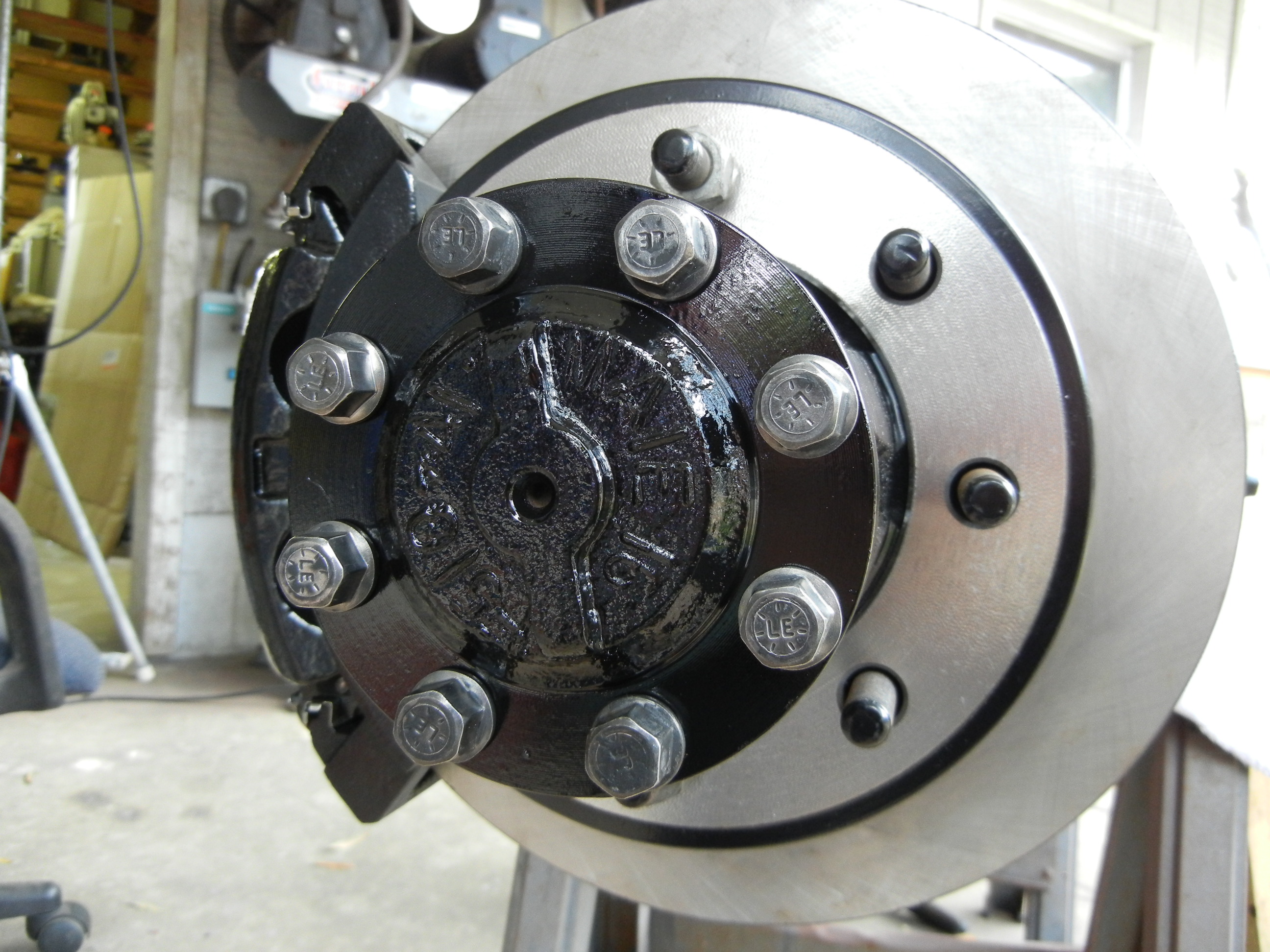
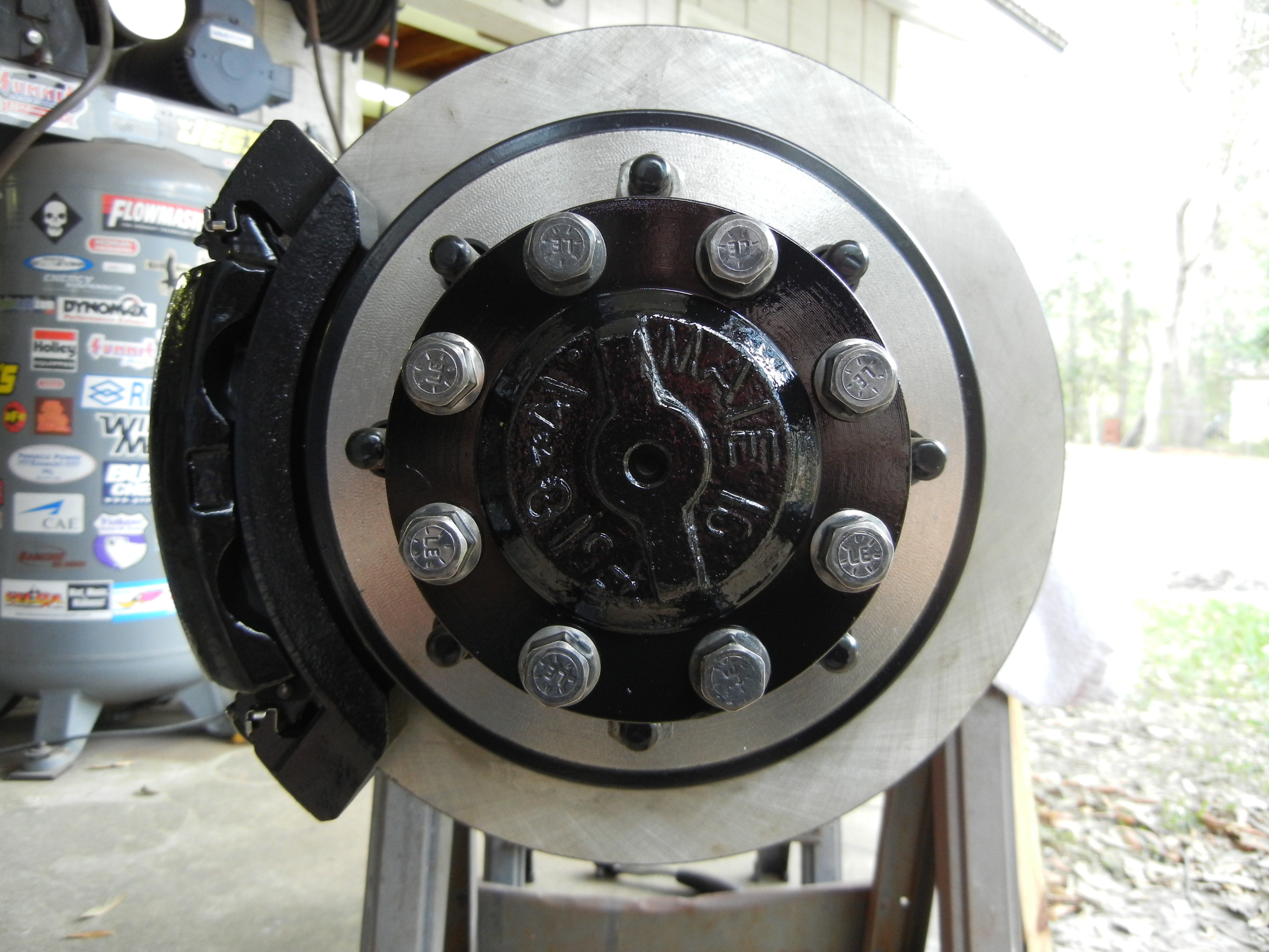
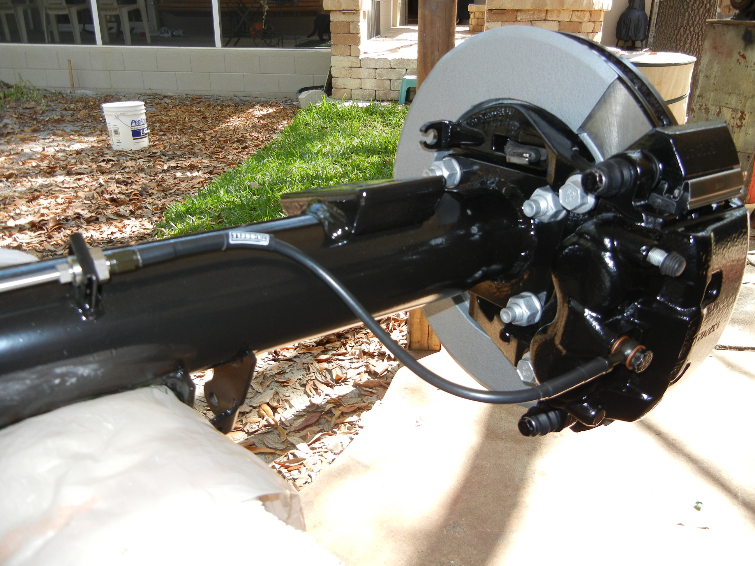
The wheel hubs and hub spindle nuts which were from the
Sterling's disc conversion donor D60 found their way back on this D70 axle. Then
went on the rotors, caliper brackets and calipers.
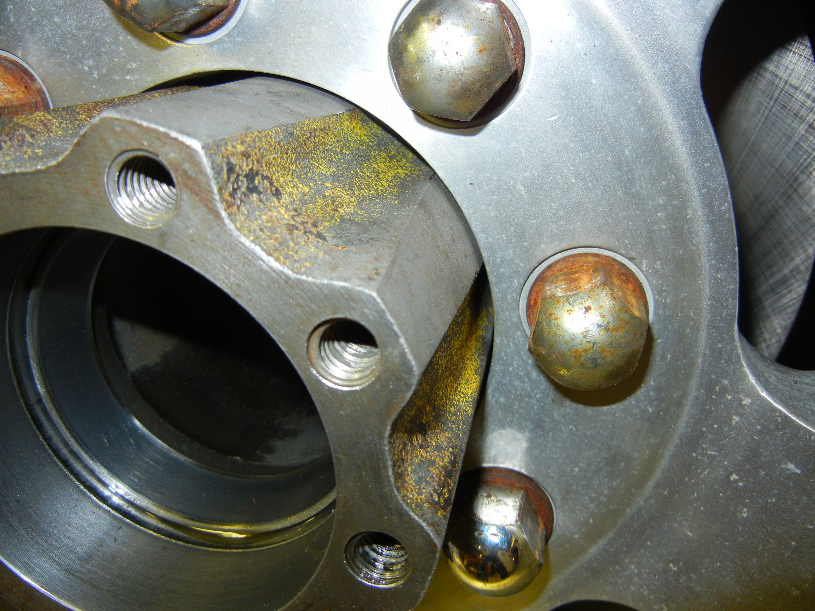
Another item I really liked were the grade 9 axle shaft bolts that came
factory on the D60 axle. Since we used the last set on the Sterling conversion,
we went back to the junkyard and got another set of 16. Don't worry though as
the axle these came off was only drum brakes and not to mention someone already
took the axle shafts and R&P. They just left the bolts on the ground. How
convenient! These are much better than the crappy grade 5 that came with the
axle.
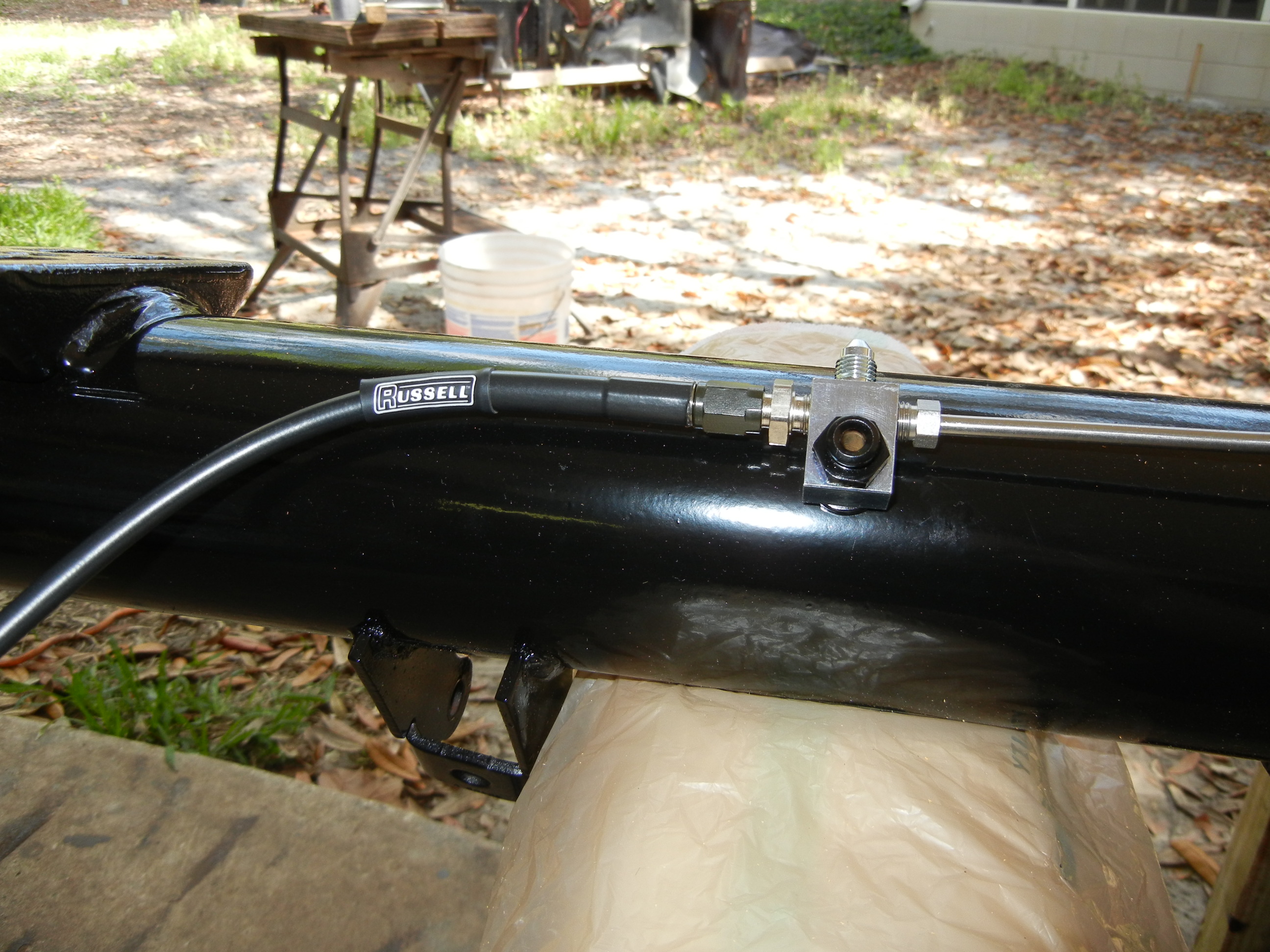
Now was a good time to test out the tubing straightener my father made. He
built this after we decided to make our own brake and fuel lines out of
stainless steel. The first piece was the "up and over" section on the housing.
Russell DOT approved brake lines were also used.
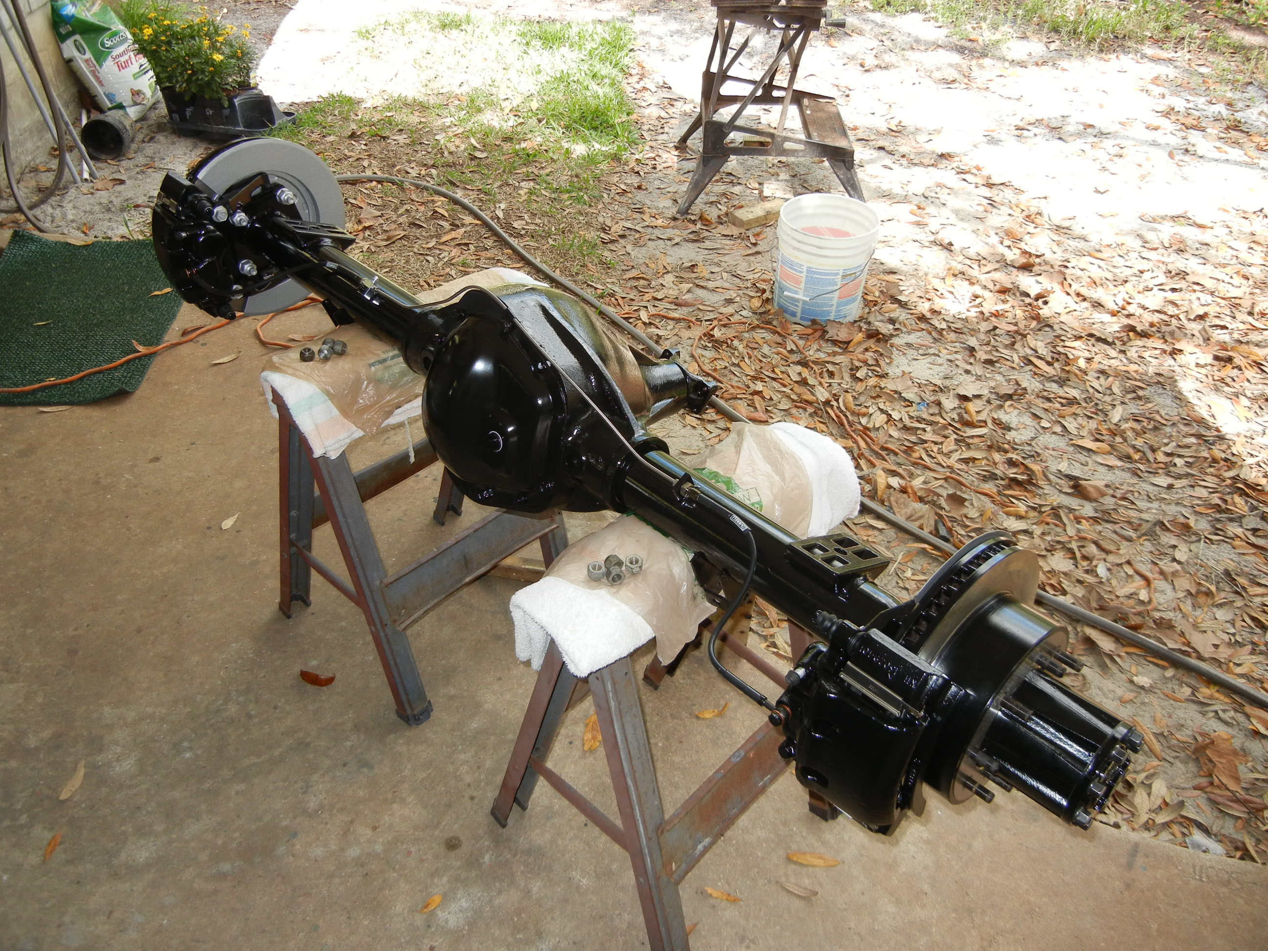
Finally the axle was finished!