Part 1:
It's nice that Ford finally added rear disc brakes to the Super Duty trucks and
vans in 1999. But what about those who have the 1992-97 style F250 and 350
trucks? Surely they would like the same braking performance.
Well instead of using the typical Caddy single piston calipers, Chevy 3/4 ton front rotors and custom caliper brackets that so many shops offer (www.tsmmfg.com whose kit sells for $709.95), you can have the brakes Ford currently uses and still remain true to the OEM design/specs.
The objective here is to convert my Father's 1997 F-350 from rear drums to rear discs. We poked around a few junkyards and stumbled upon several late model Ford airport shuttle vans with Powerstroke engines and full floating Dana 60 rears which all had disc brakes. Looking at my brother's 2001 F250 we noticed the brakes were very similar, just that the truck's calipers were finned while the van's were not.
Right away we knew this was not going to be a "bolt on kit" to get the van brakes onto the truck axle. The reason we went with the van brakes is because the vans still retain the 8 on 6.5" bolt pattern of the lugs, whereas the SD is the 8 on 170mm. Not having to buy wheel adapters saved us an arm and leg, not to mention the junkyards in our area are full of vans, not Super Duties.
When the time came, we basically got the whole rear axle from a 1999 E350 with 256k on the odometer. About $120 for the whole thing from a major you-pull-it auto salvage yard called LKQ in Orlando and we were set. Yes we actually did get the axle and brakes that cheap since we went to the junkyard over the Thanksgiving holiday weekend and everything was 50% off!
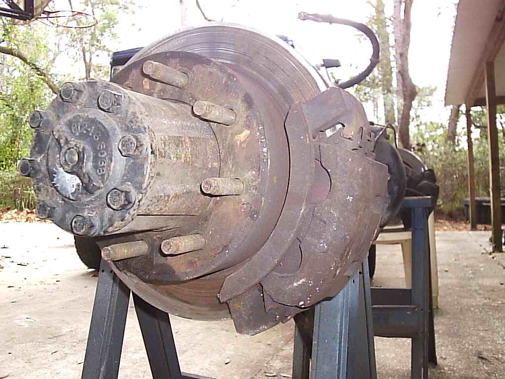
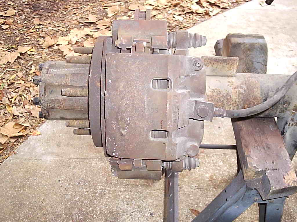
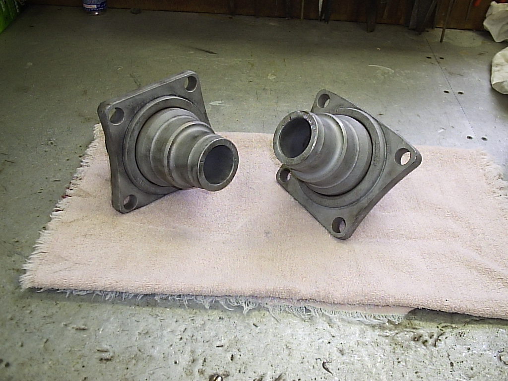
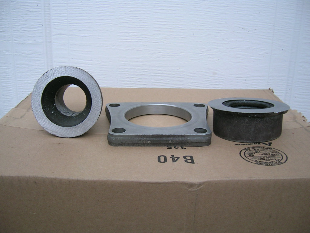
Now with the Dana 60 home we inspected it again to make sure all was well. The Sterling's drum backing plate is held on by a 1/4" thick square flange welded to the tube on one side (see part two for pics), whereas the D60's caliper bracket is held on by a 5/8" thick trapezoidal flange which also happens to be forged steel and is heat shrunken onto the tube and welded to one side (more on the heat thing later). Below in part 2 are some specifics that relate to the position of the caliper brackets in relation to the spring perches. Before we cut or machined anything we carefully referenced the angle of each caliper bracket so that they could be duplicated later on the Sterling axle.
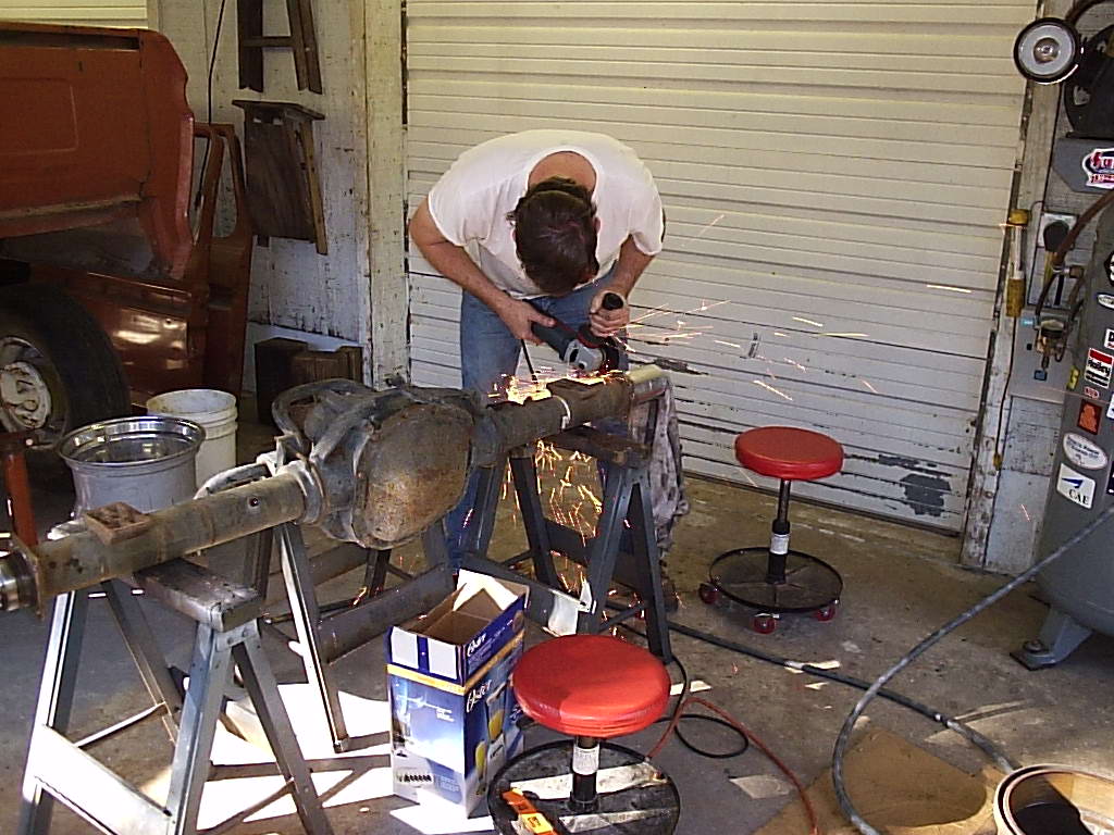
So our initial guess was that we were just going to take the Sawzall and cut the weld off which would free the D60 flange. Then before attempting that we thought lets just chop off the spindles and have a buddy with a big lathe take off the welds.
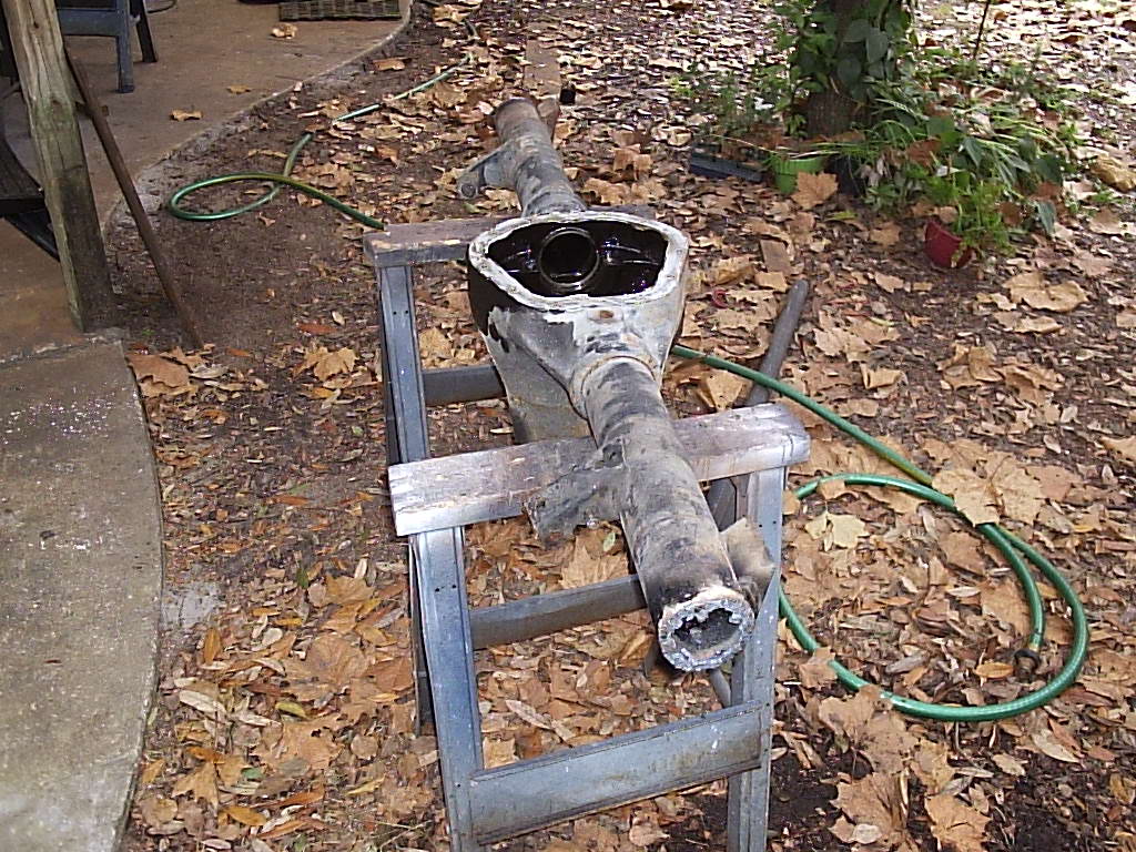
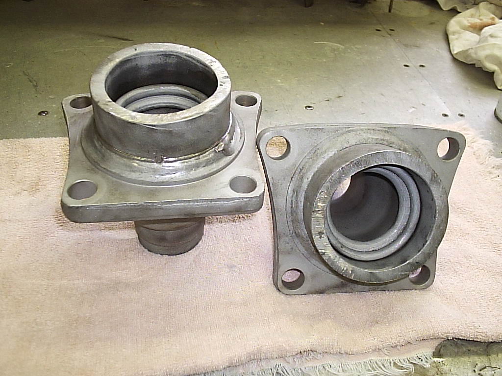
With the help of some friends who have a huge machine shop, a few
turns on the 13"x40" lathe and some fidgeting in an industrial
Rockwell band saw and the flanges were free of the tube. We also
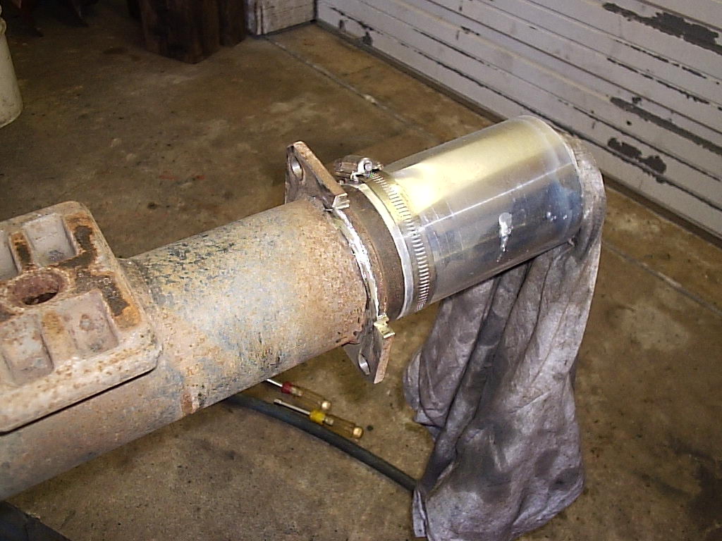
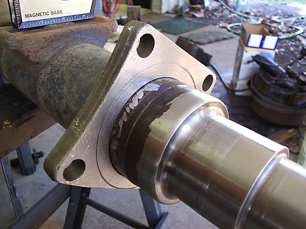
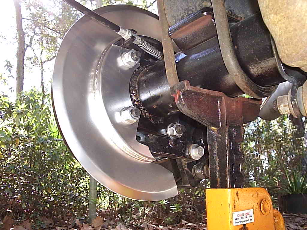
figured out how the spindle of a 1-ton rear axle is held in by the tube: it is
friction welded in place. Above in the bottom right pic you can see the rolling
out of the two metals. Ok so then the outside weld blob is machined off, then
the flange is placed over the tube while glowing red hot and allowed to shrink
as it cools on the tube offering an extremely strong fit. The outside weld
is then added for assurance.
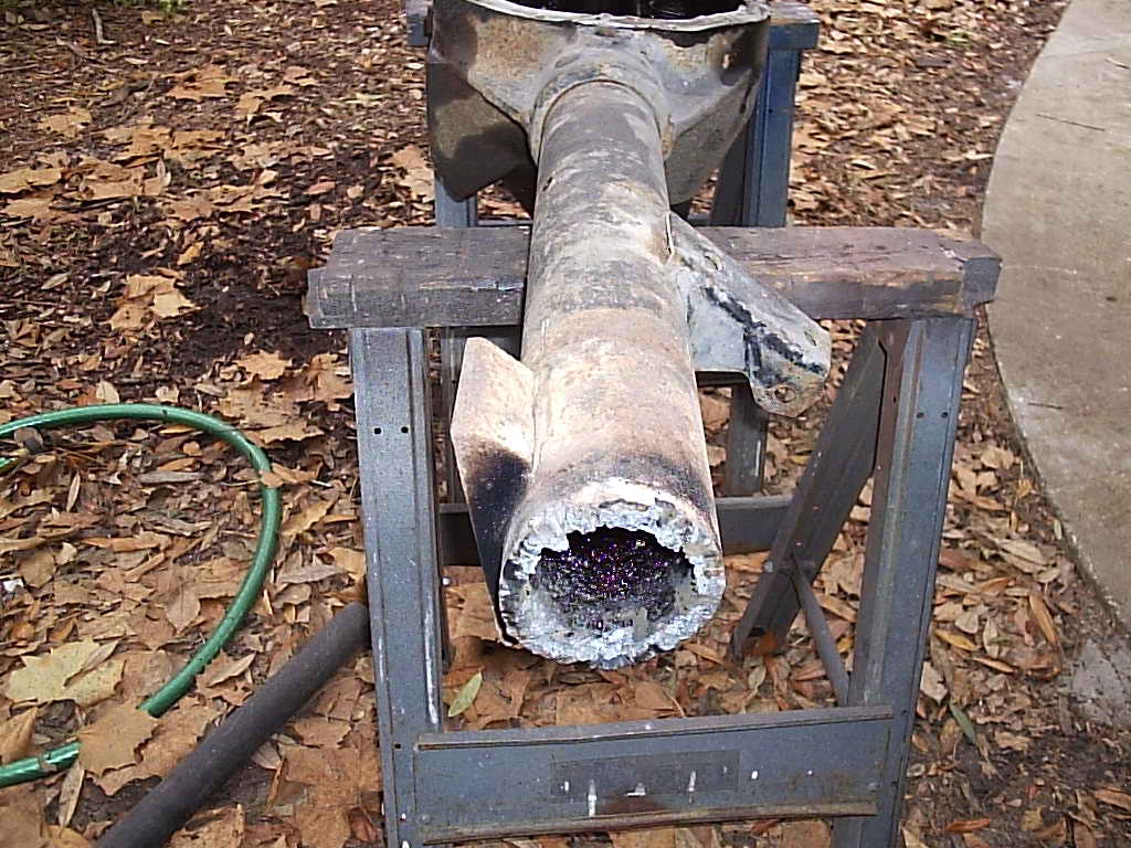
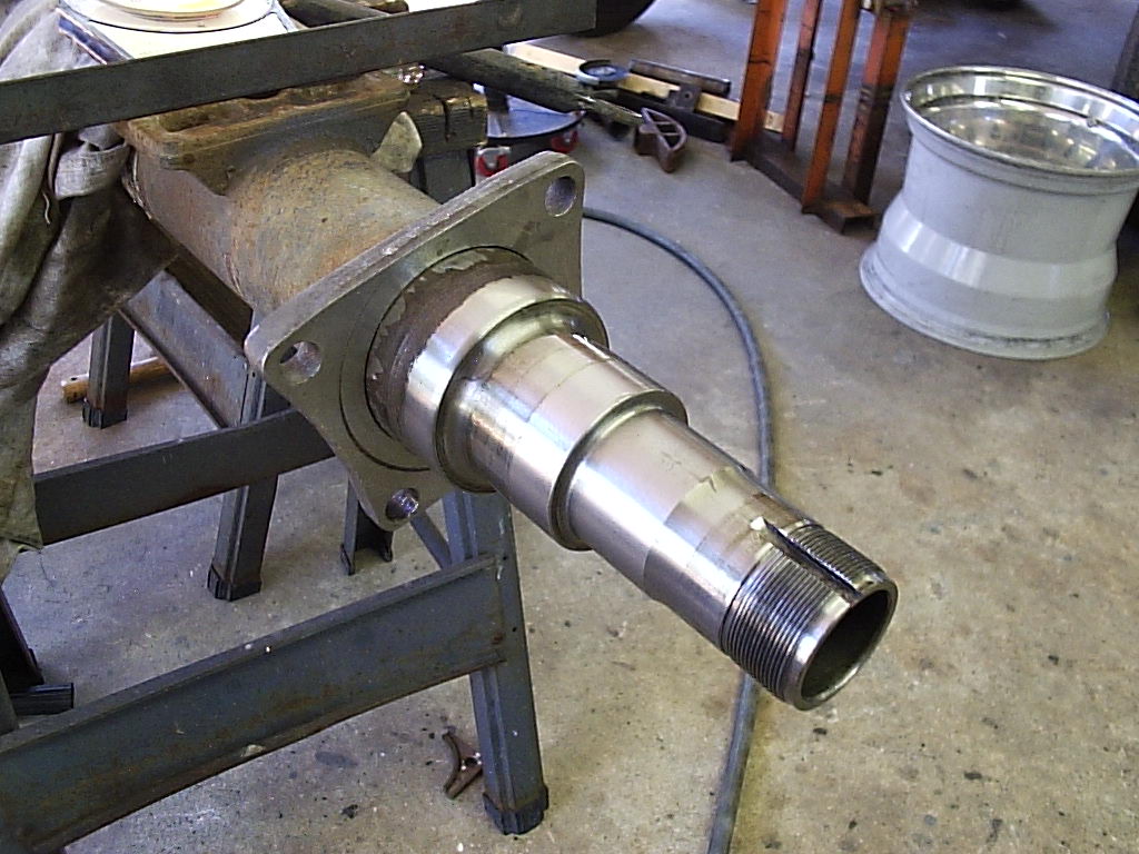
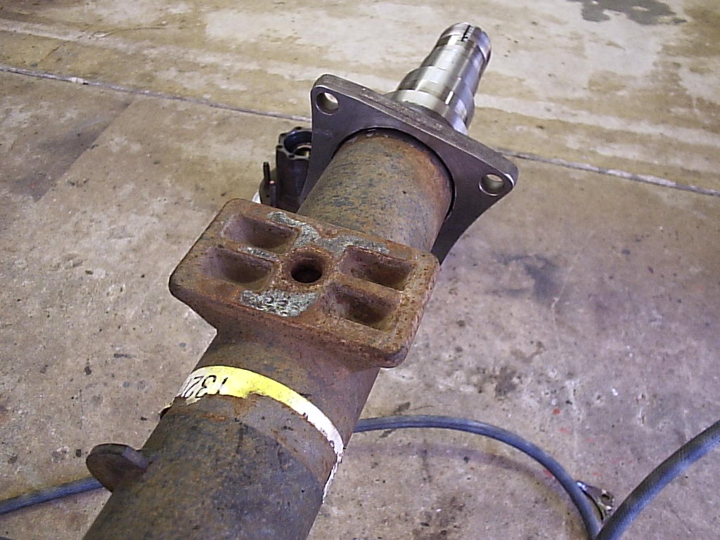
So as is turns out, you will never be able to separate the spindle/tube from the
flange because of this assembly method. The only thing possible is to just
machine it off and then bore out the hole to exactly (or a few thousandths over)
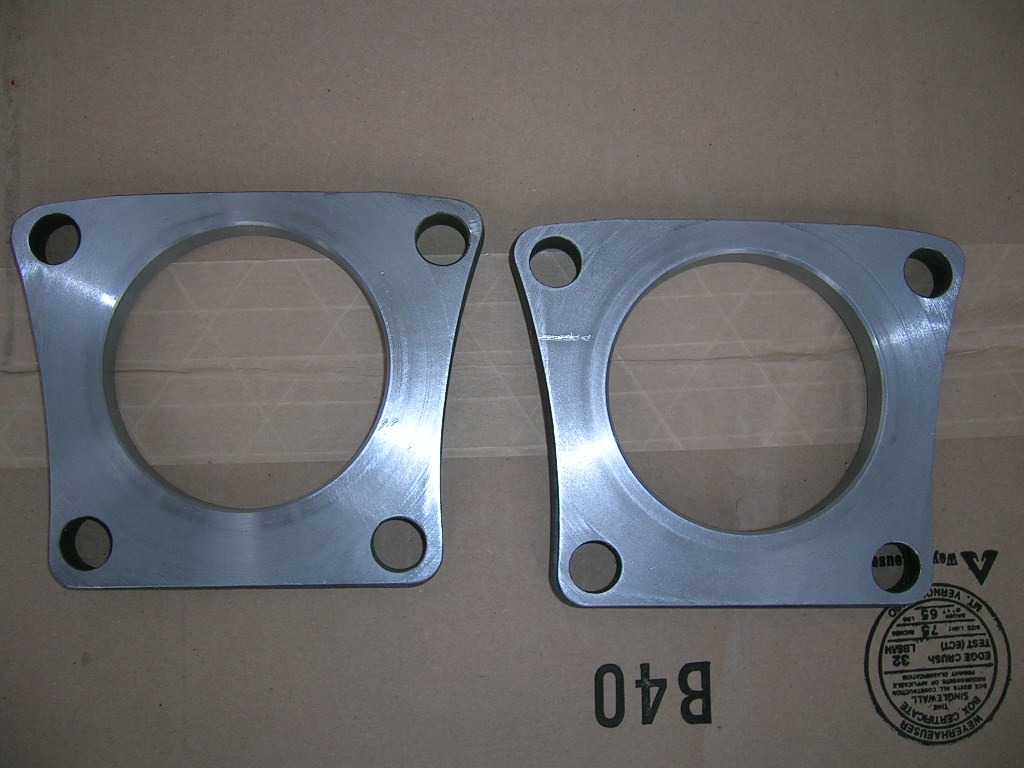
3.5" to match the Sterling's tubes. In the above photos you will notice a
centering ring on the spindle side which centers the caliper bracket, well the
machinist thought we didn't want this so he knocked it off. It's ok though as
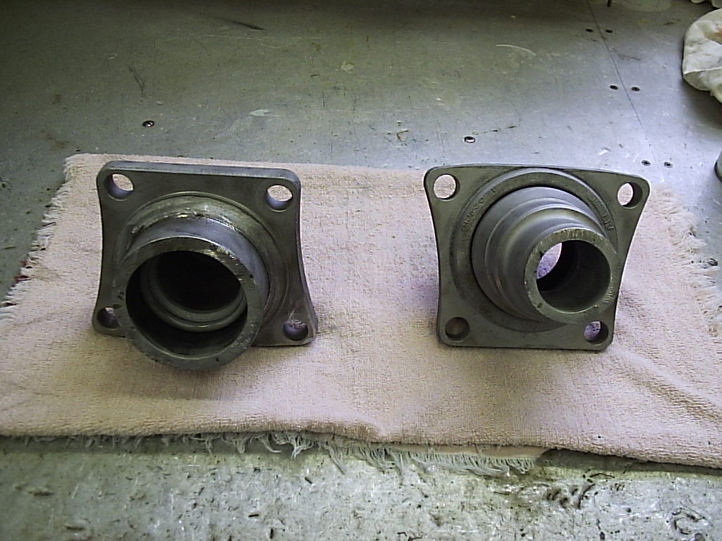
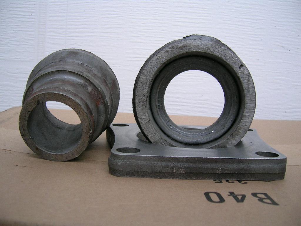
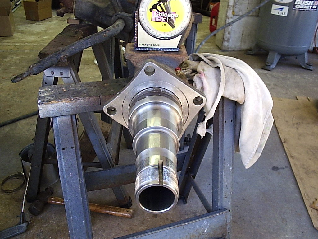
the studs do a perfect job of keeping things centered. And finally this is what
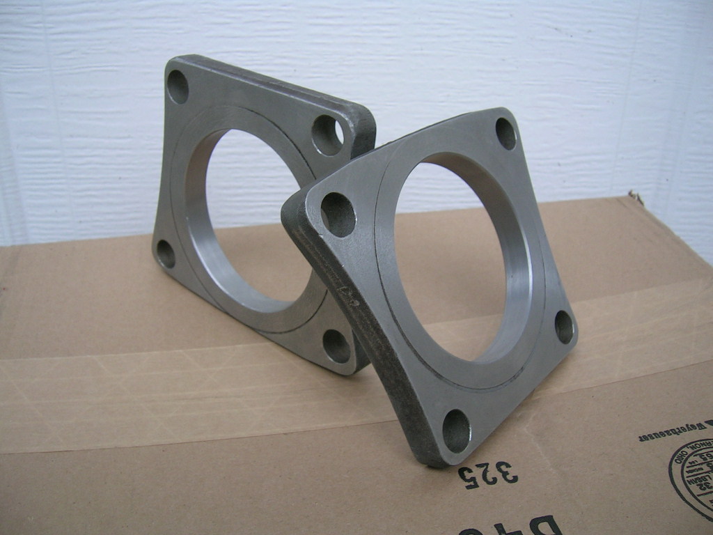
we ended up with:
As you can see the final flanges are beautiful but came at a expense of a few man hours behind a lathe and band saw. Might I just recommend to you making new flanges out of mild steel, and 1/2" thick would be sufficient instead of Dana/Ford's 5/8". This would save you from ruining a good axle housing like we did.
Ok by now you have either too much time or money invested to back out. Really the hardest part is over because when you see the size of the flange on the Sterling and how easy it is to remove, you're gonna laugh.
Part 2:
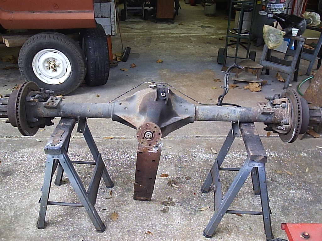
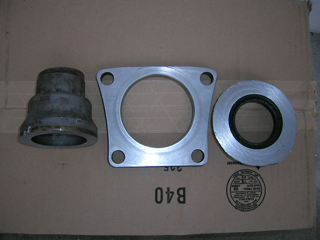
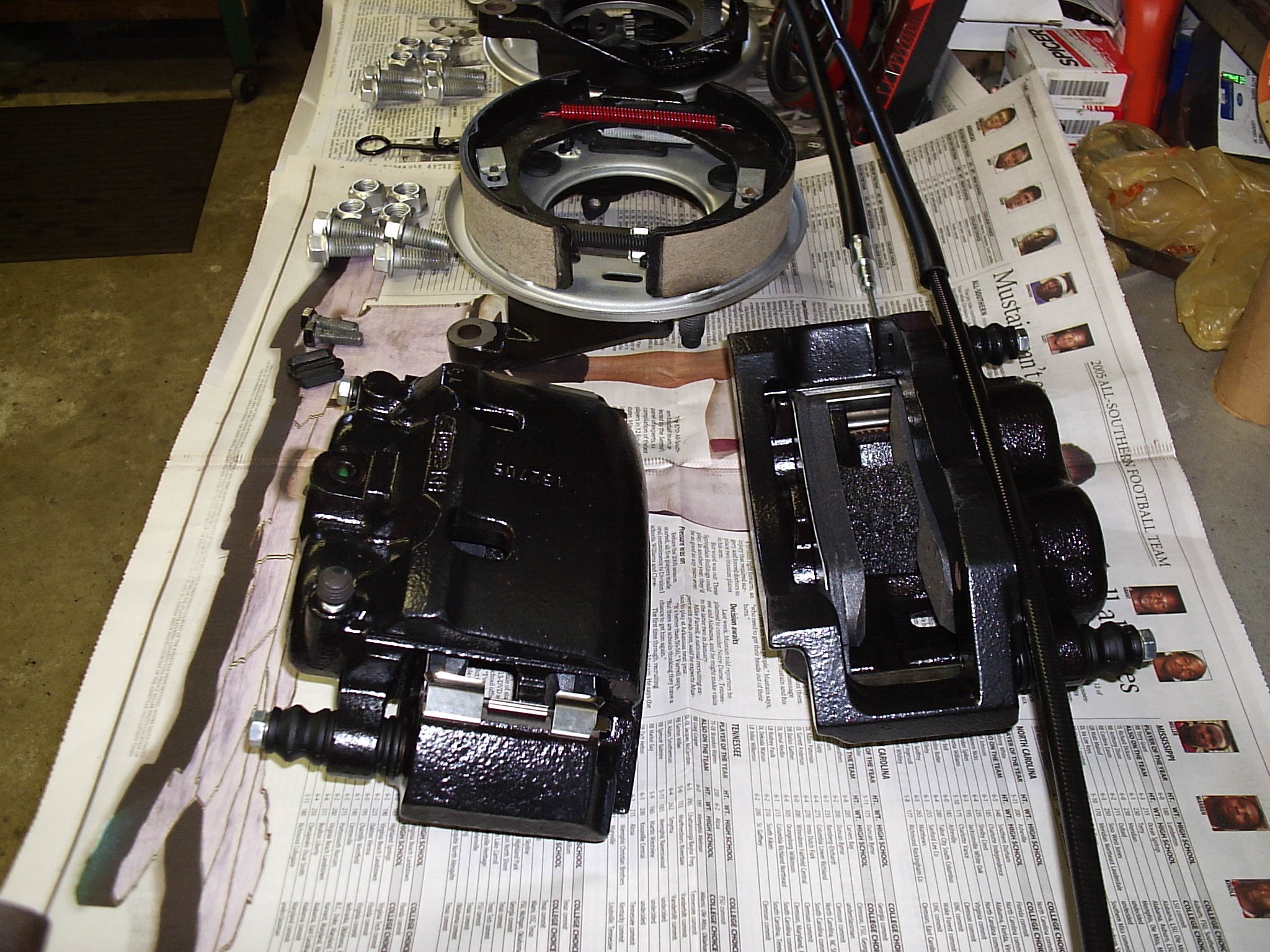
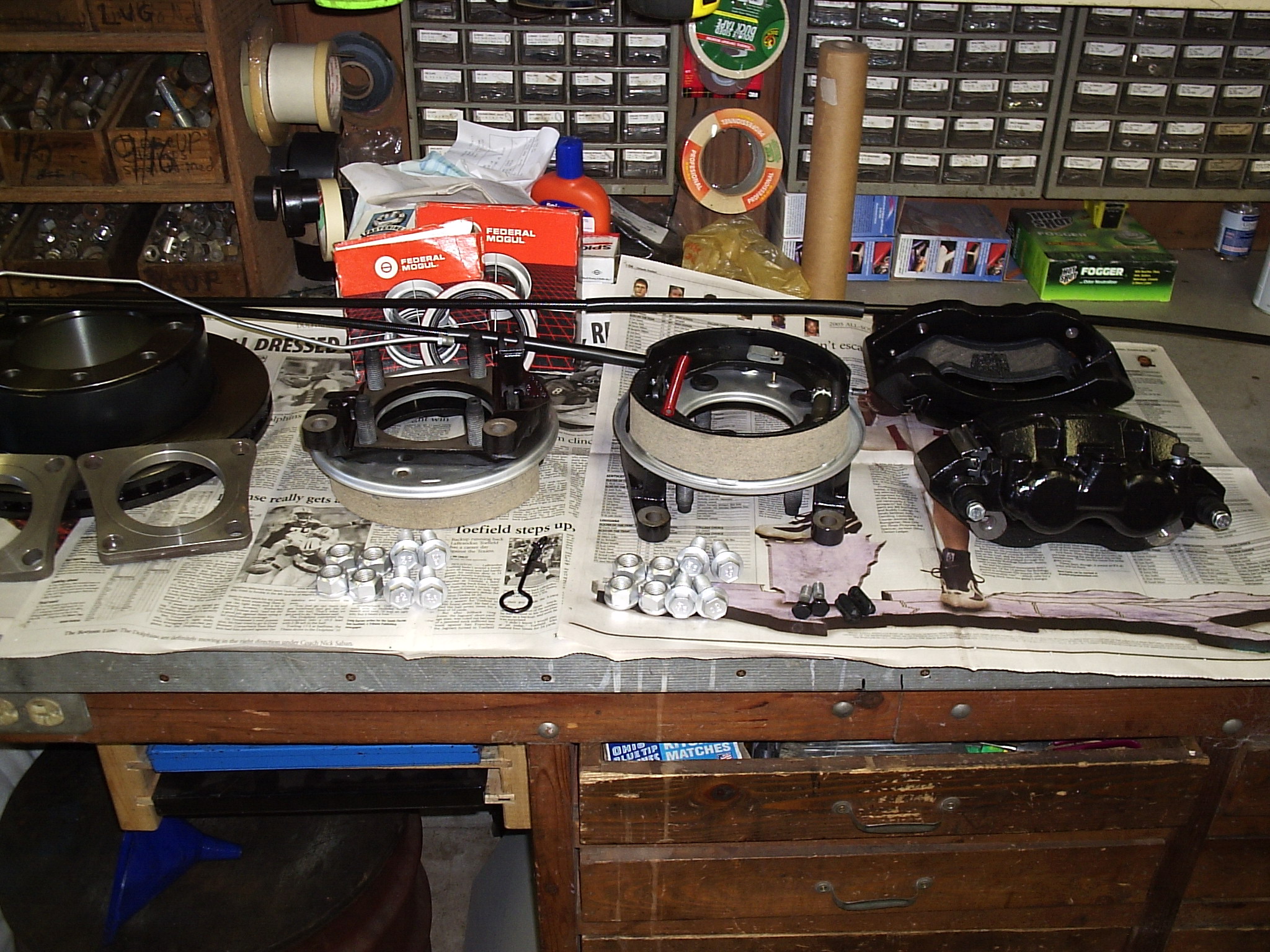
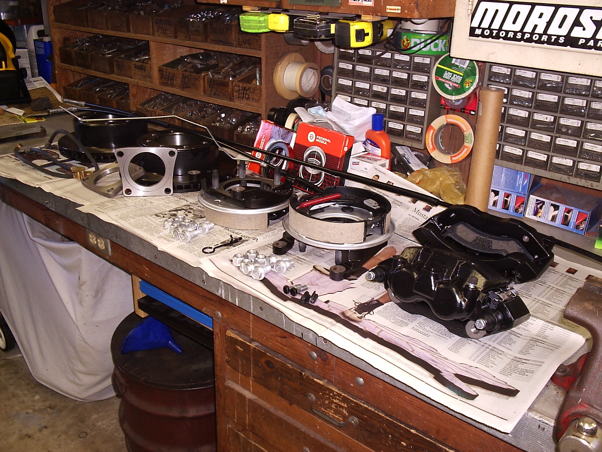
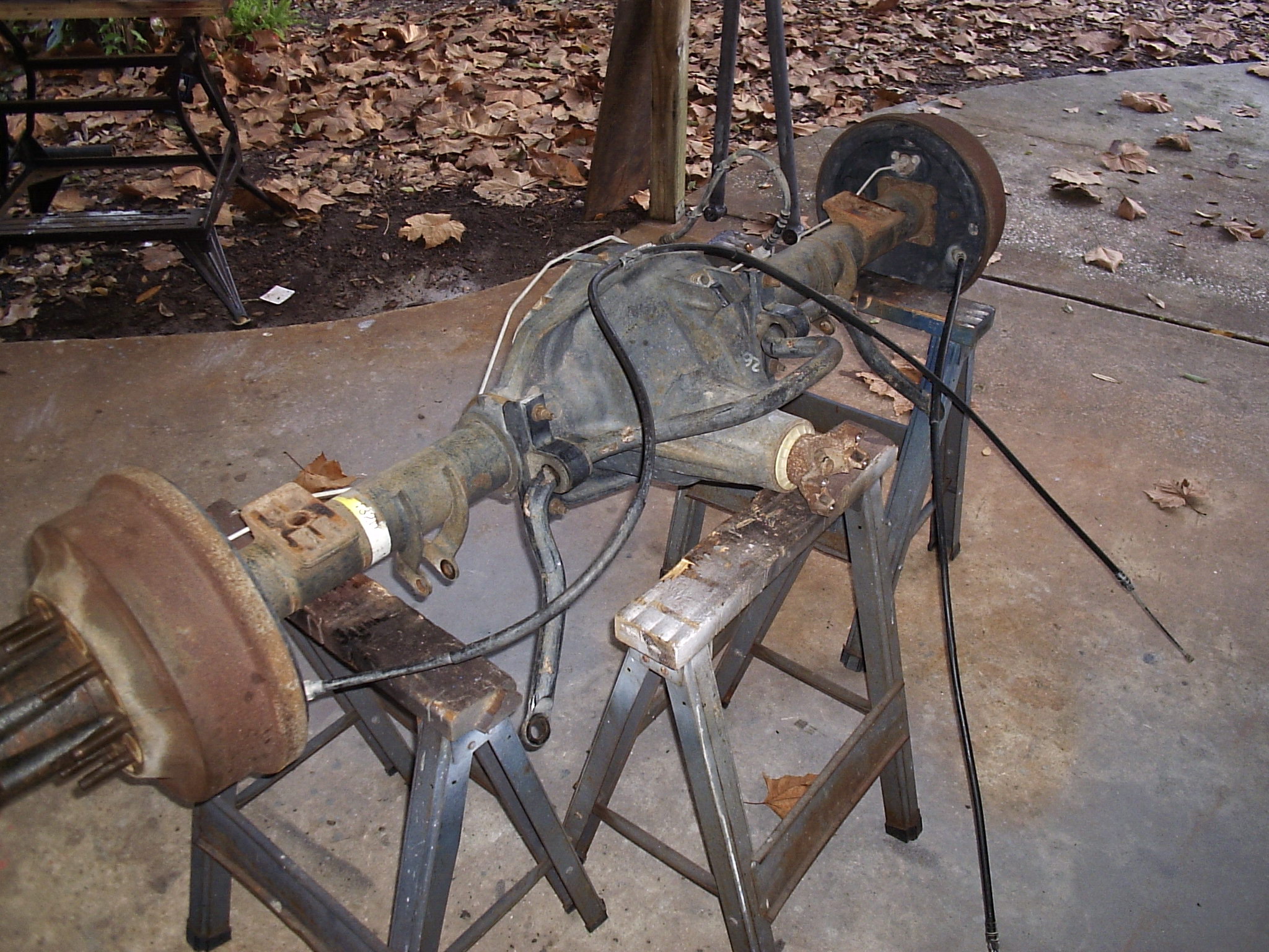
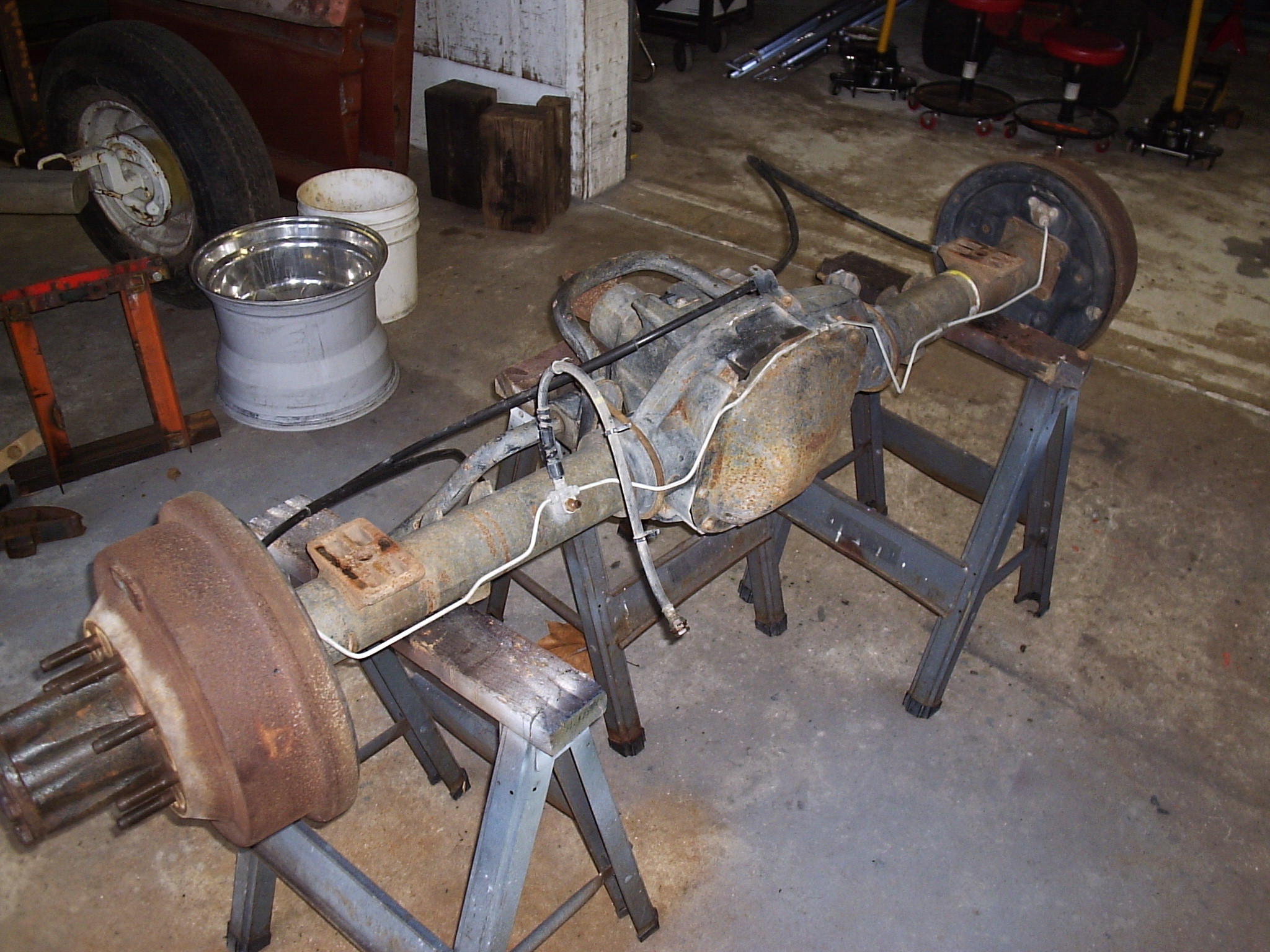
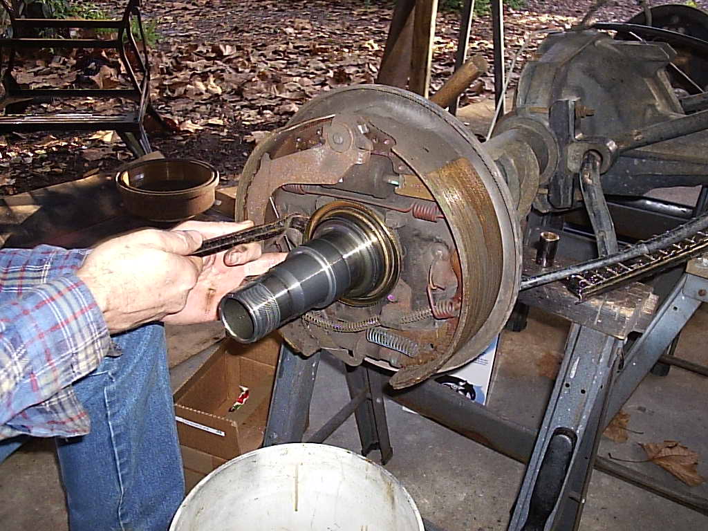
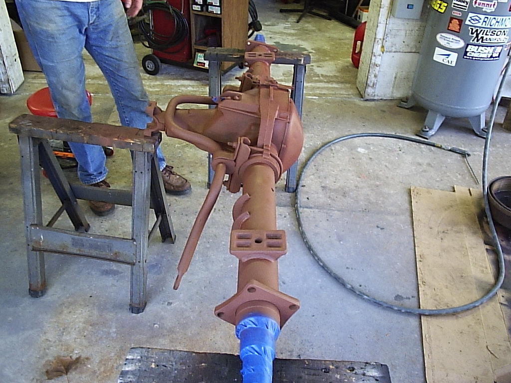
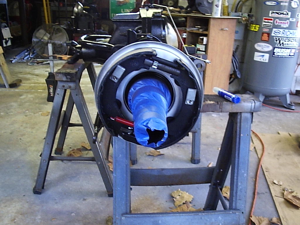
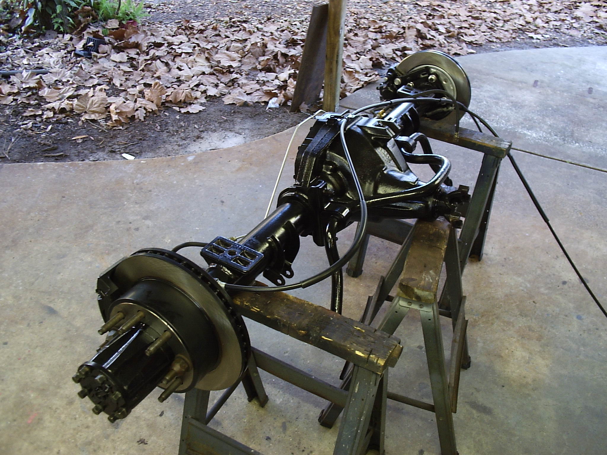
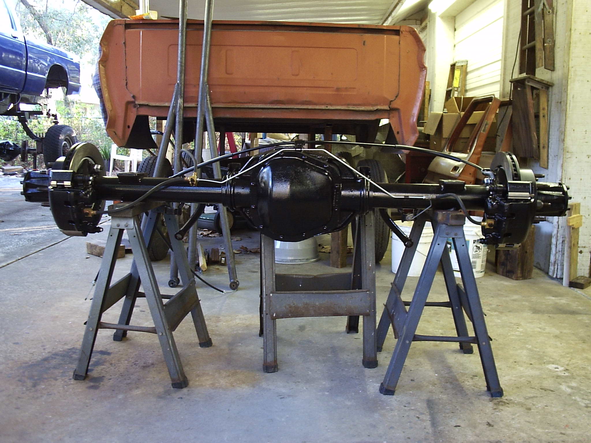
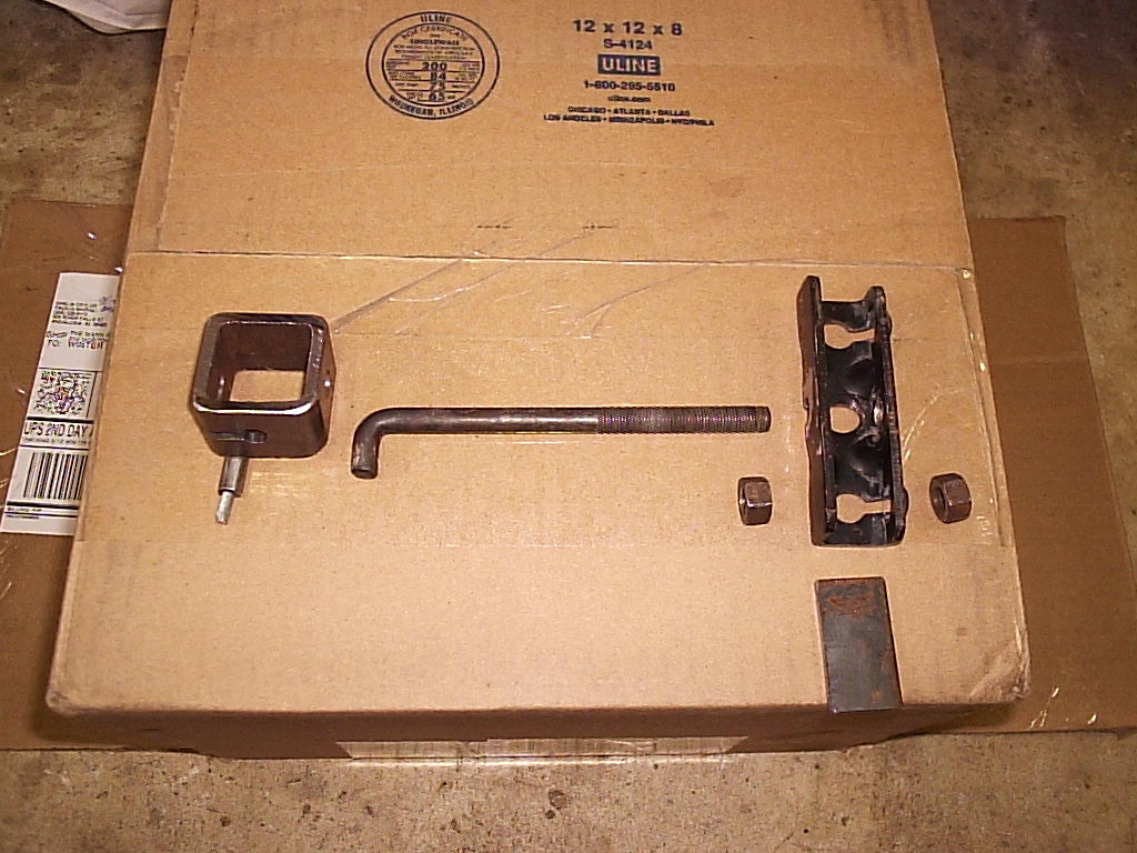
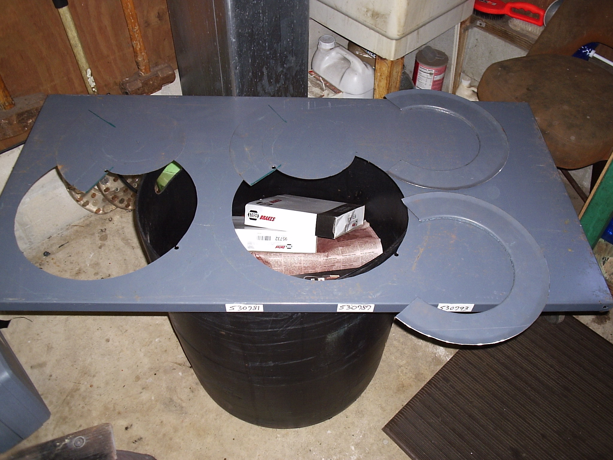
So now your bench should look something like this if you have already
collected all the parts from your nearest auto parts store, or online:
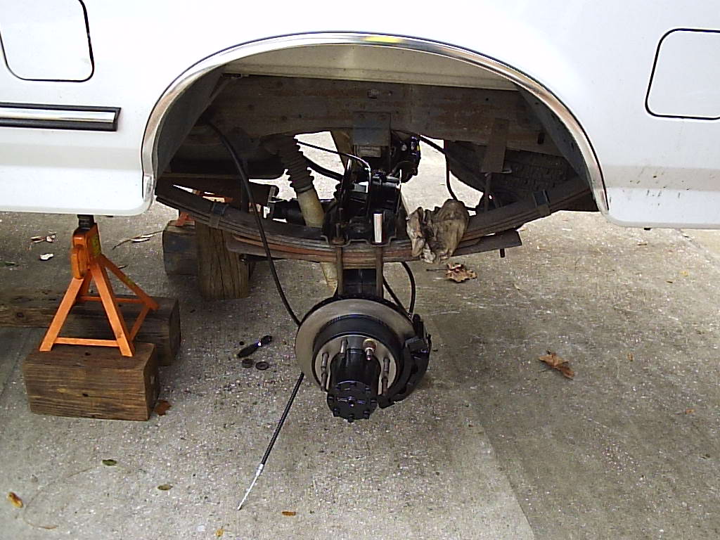
Take a few days off from work, or do what we did and work over the holiday break. Trust me you will need the time for unexpected delays such as we found. Begin by of course removing the rear axle from the vehicle and setting it up on jack stands bla bla bla. Pressure washing can help greatly.
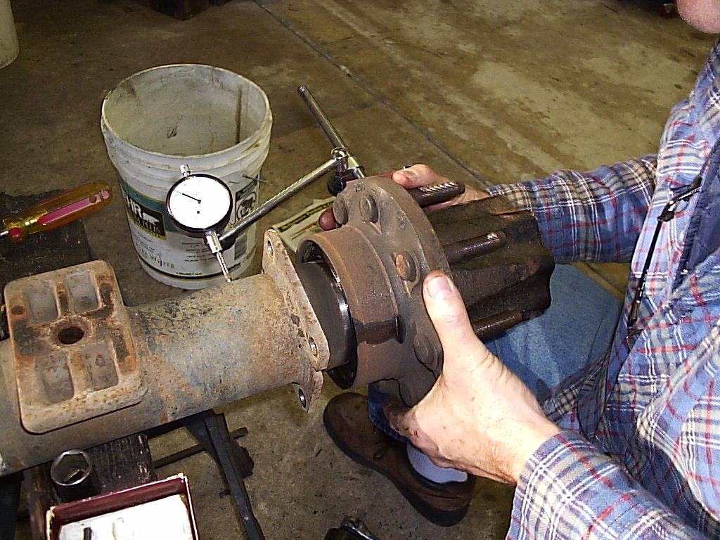
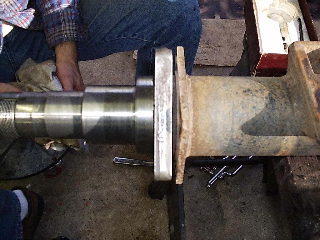
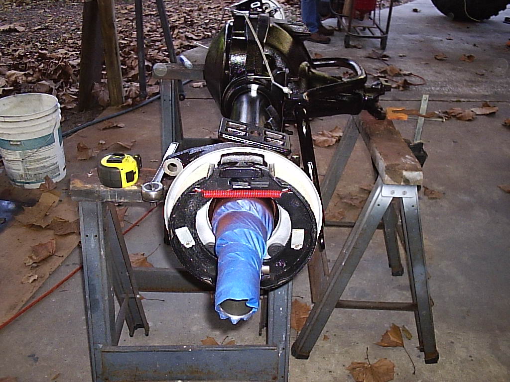
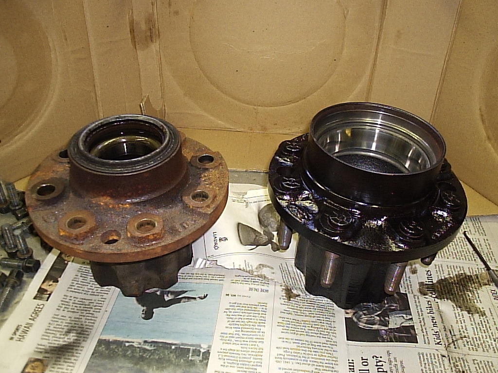
The Sterling axles have a neat oil seal unlike the Danas. Both sealing surfaces stay attached to the seal races and thus when the hub turns, the seal spins inside itself. In the last pic we checked for the tube run out. It was about 20 thousandths which isn't too bad considering when the D60 spindle and tube were in the lathe the run out was terribly wobbly. This means it will be easier to set the new flange perpendicular to the tube and keep the brake calipers in alignment over the rotor.
Click Here to see a PDF version of the flange orientations made in AutoCAD. Click Here to see a PDF side shot of the flange assembly also made in AutoCAD.
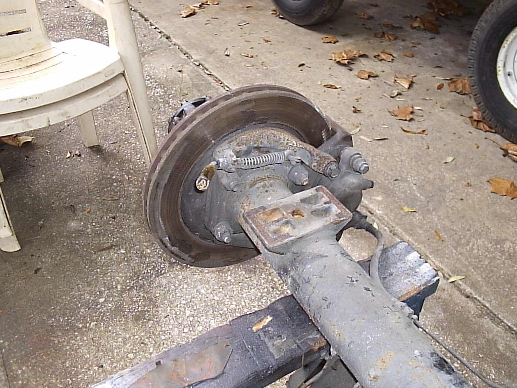
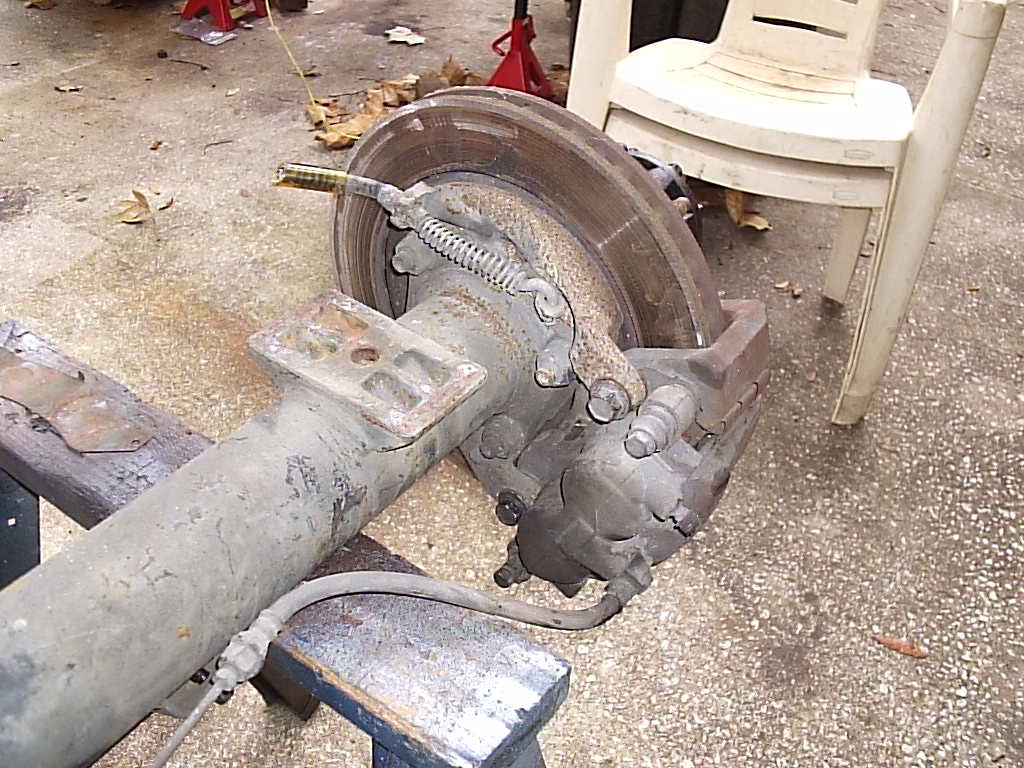
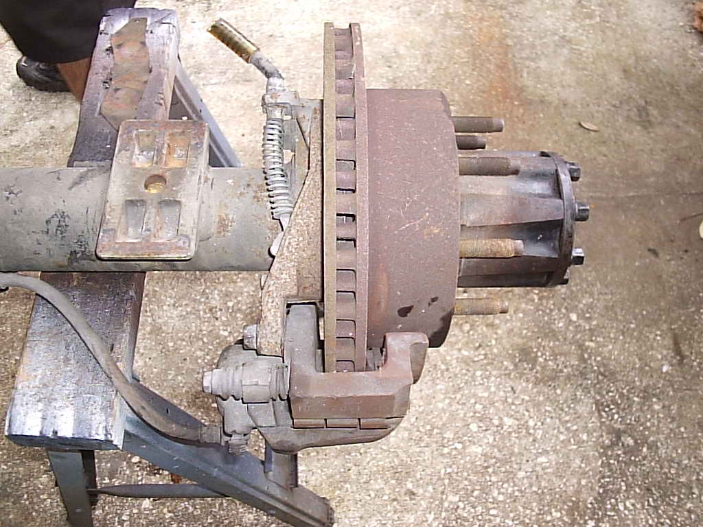
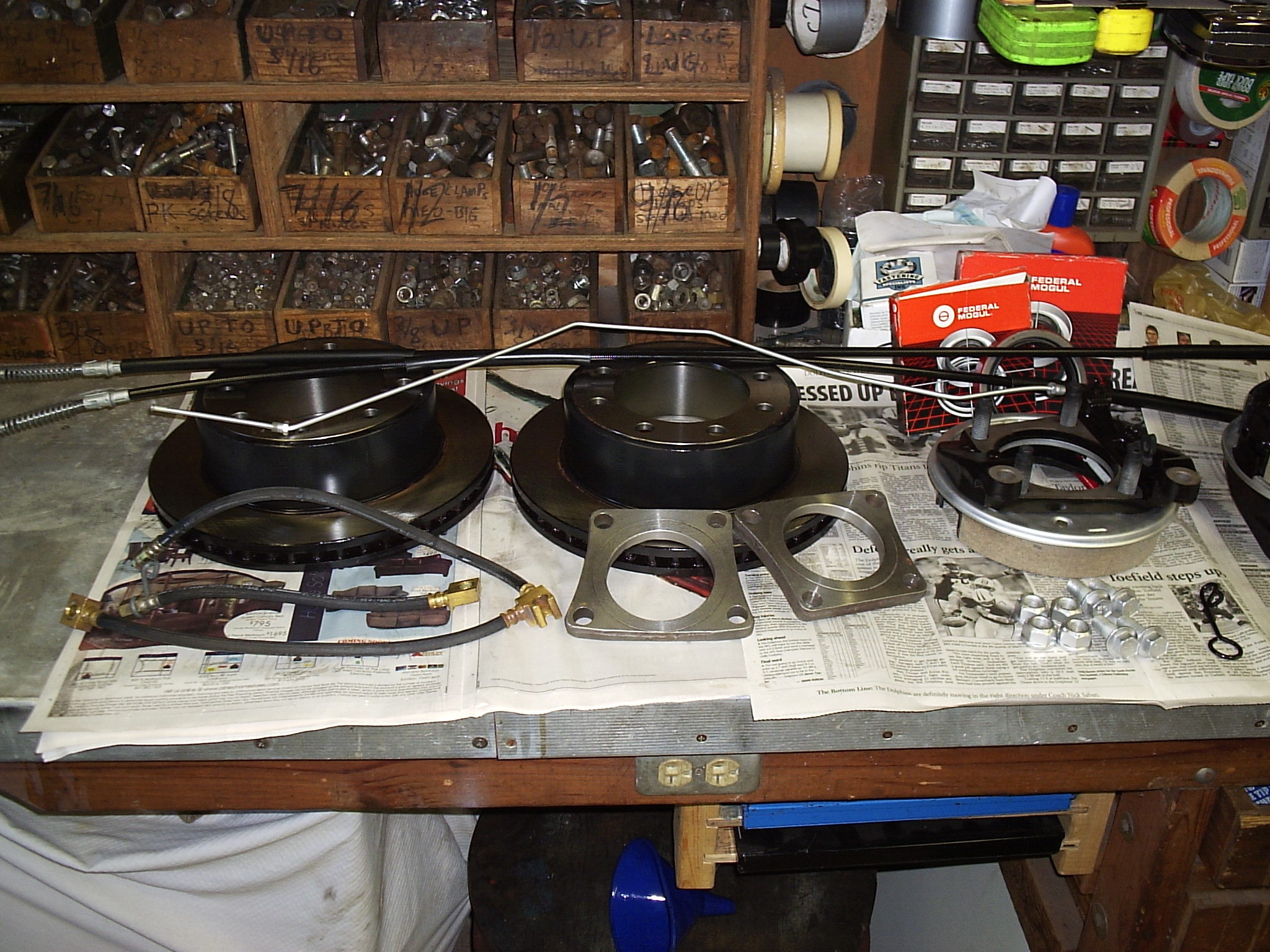
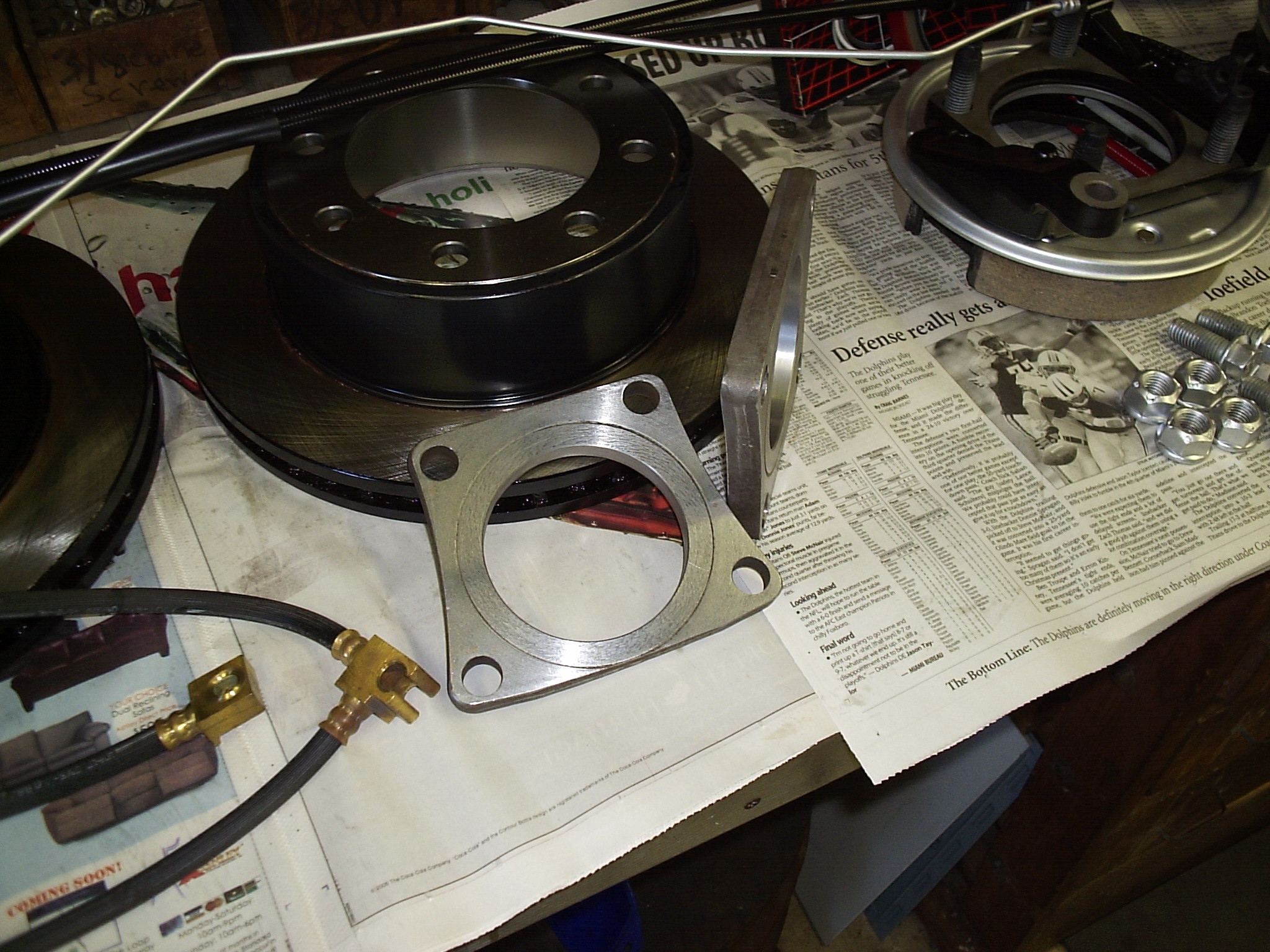
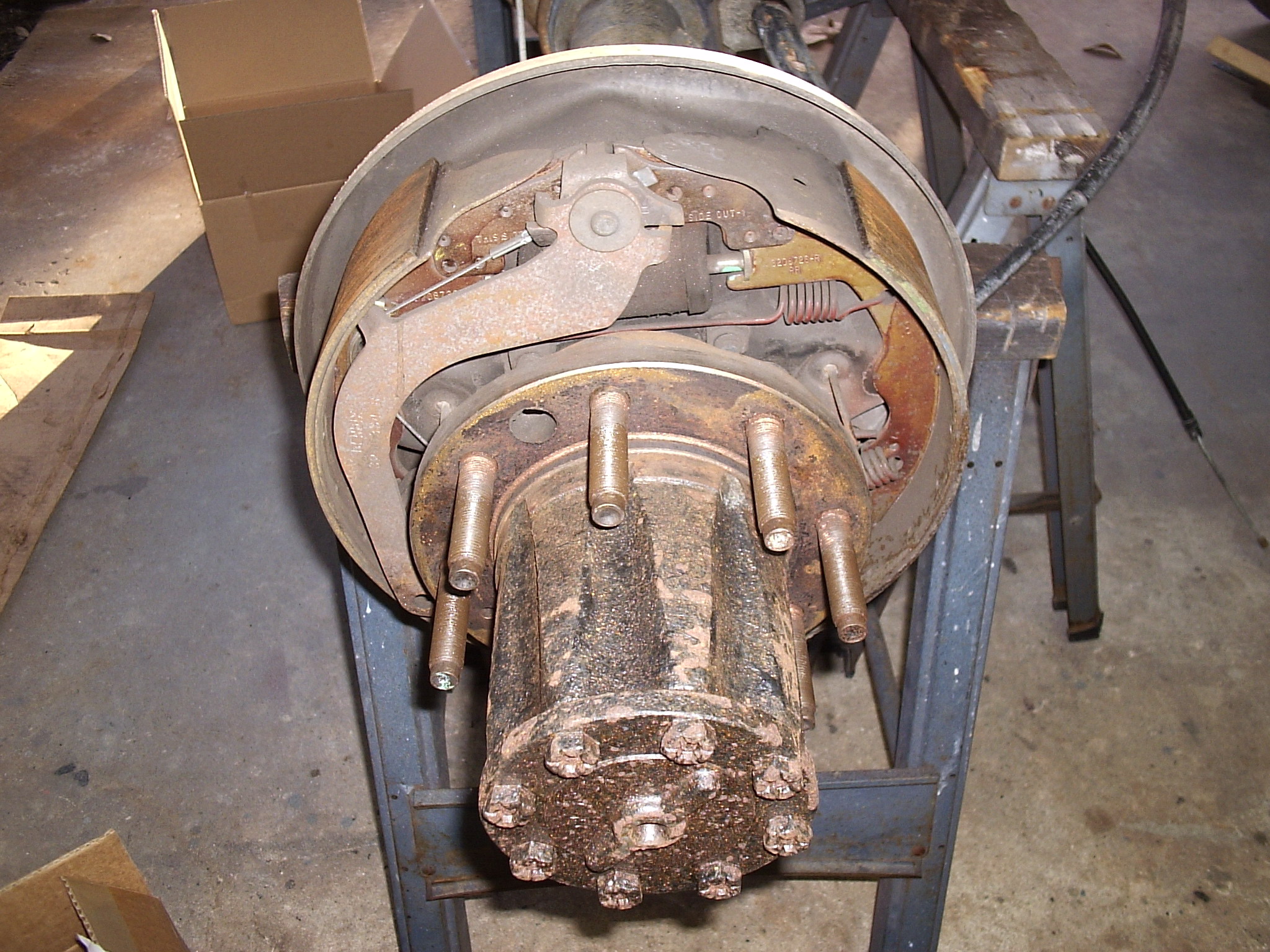
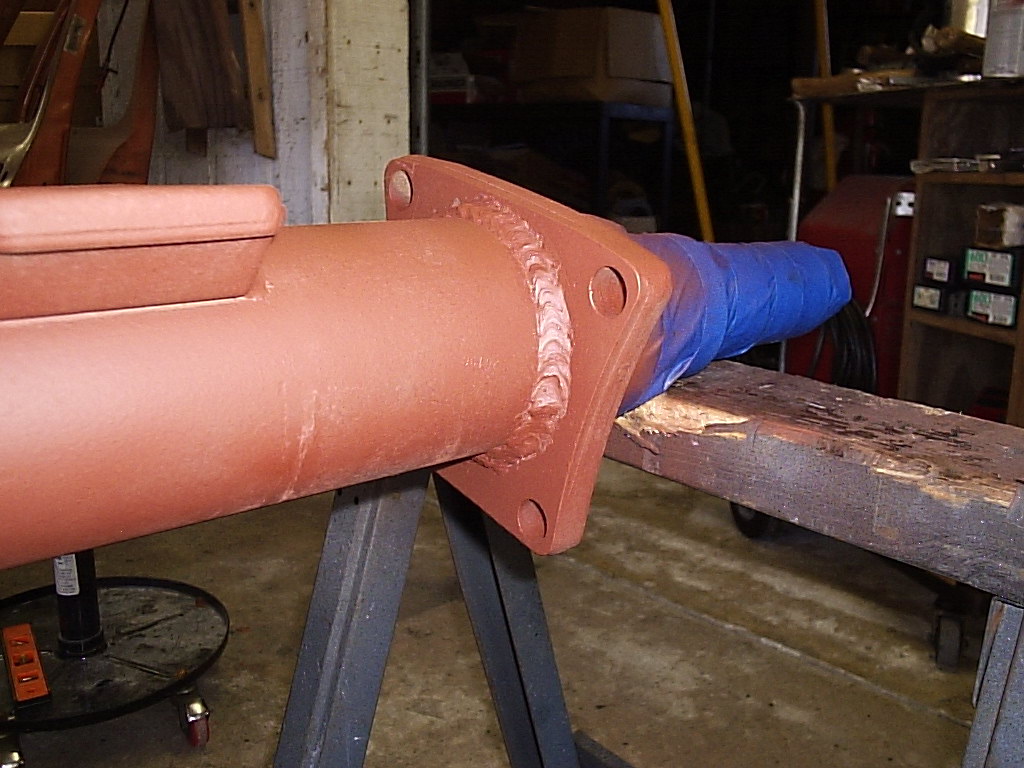
For giggles you can see how thin the drum flange is. The cut off wheel on the angle grinder worked great to remove the small weld holding the flange on. An aluminum wrap was used to protect the spindle from sparks and a swinging hammer. Then carefully grind off the flange weld but not too much as you want the new flange to fit snug over the tube. Center and set the angle according to the PDF diagram links above. The hub and bearings need to be mounted and the nut tightened to measure from face of hub to face of flange through the 3/4" hole in the hub. We used the depth gage feature on a 6" dial caliper. Now you should be ready to tack weld making sure the heat doesn't pull the flange too far out of alignment. Check, check and recheck. We did have to cut one tack weld since it pulled in too much.
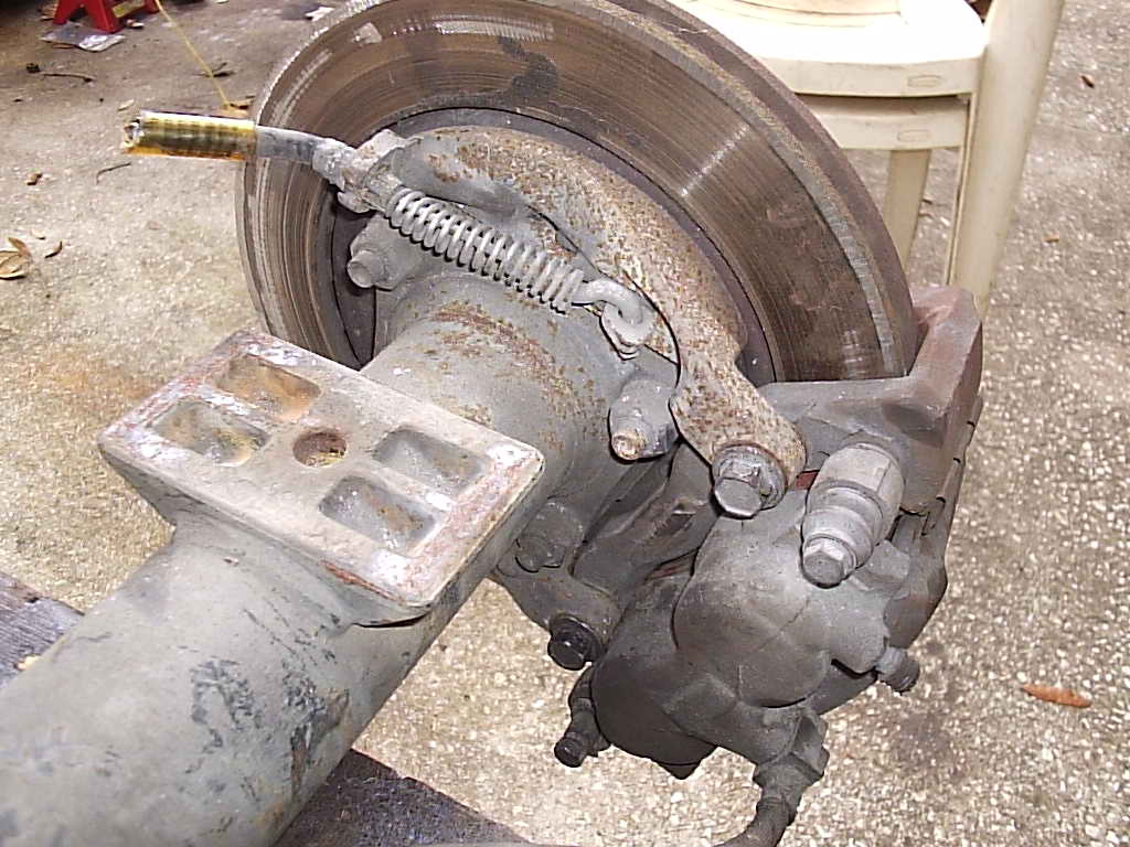
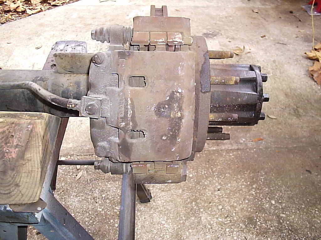
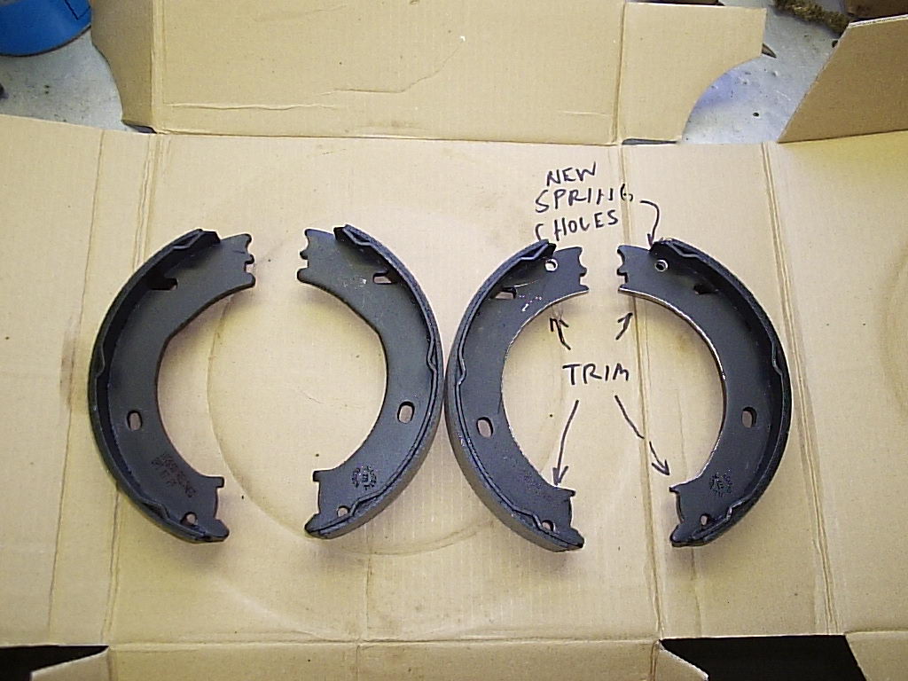
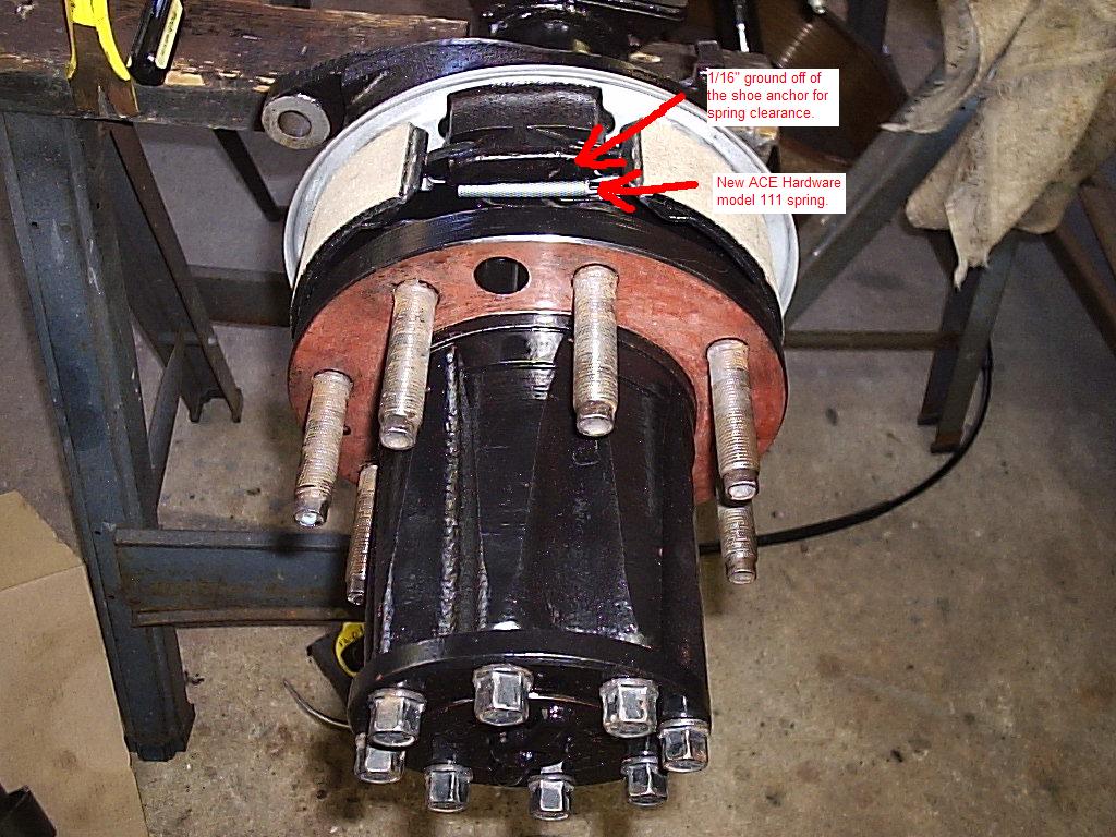
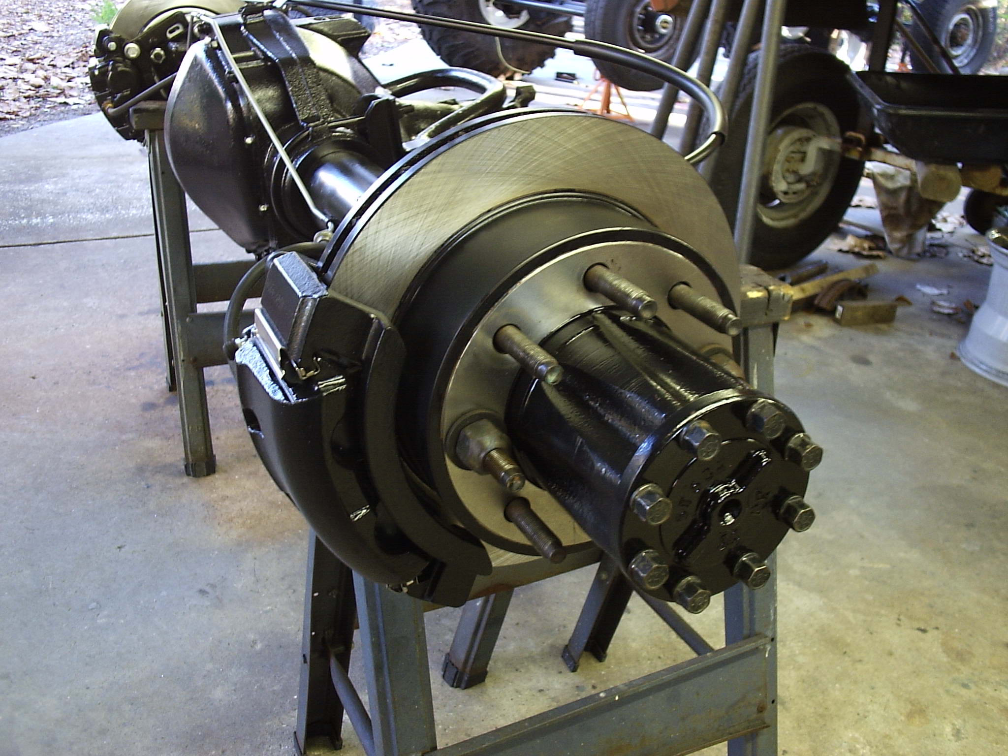
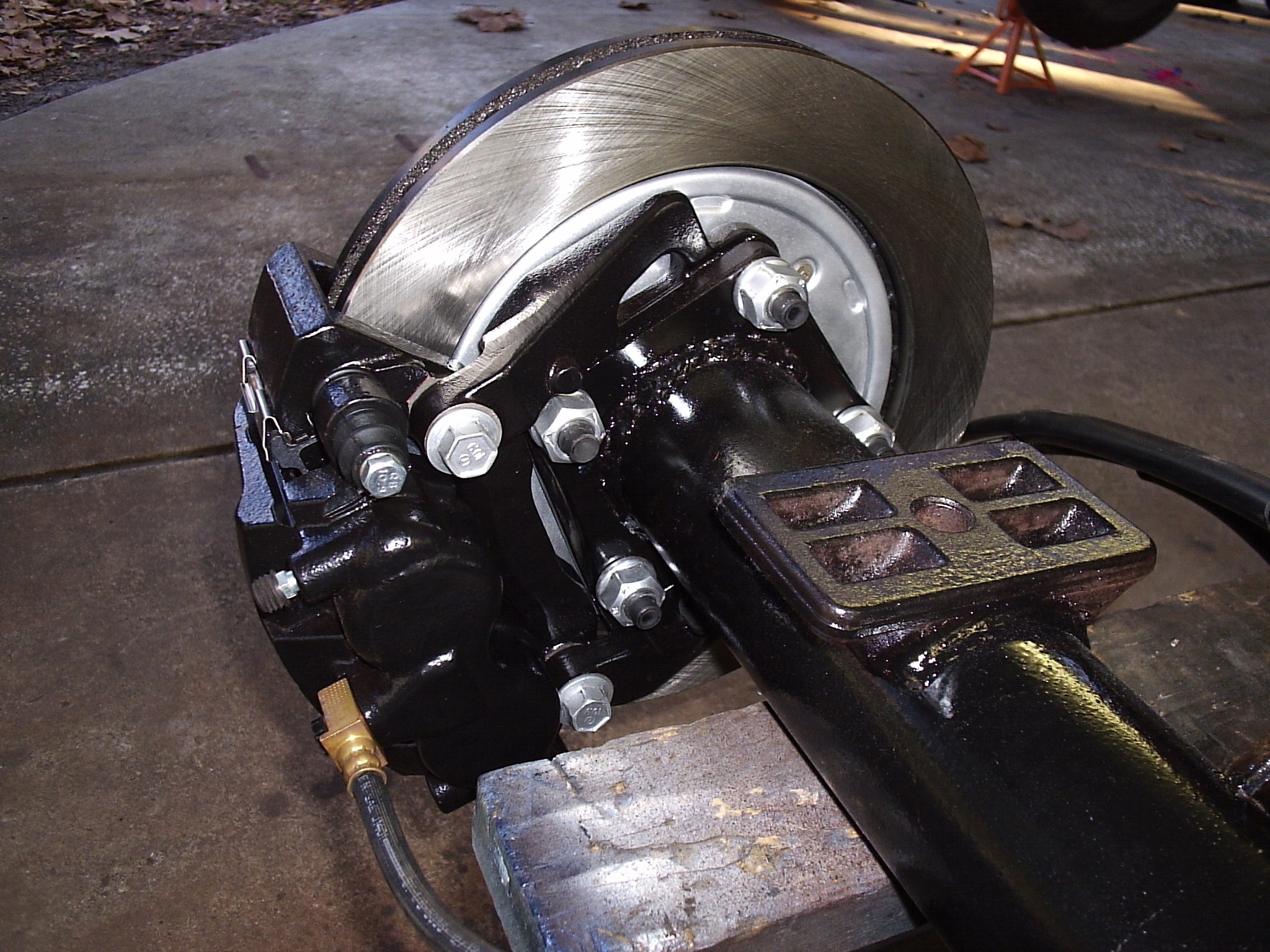
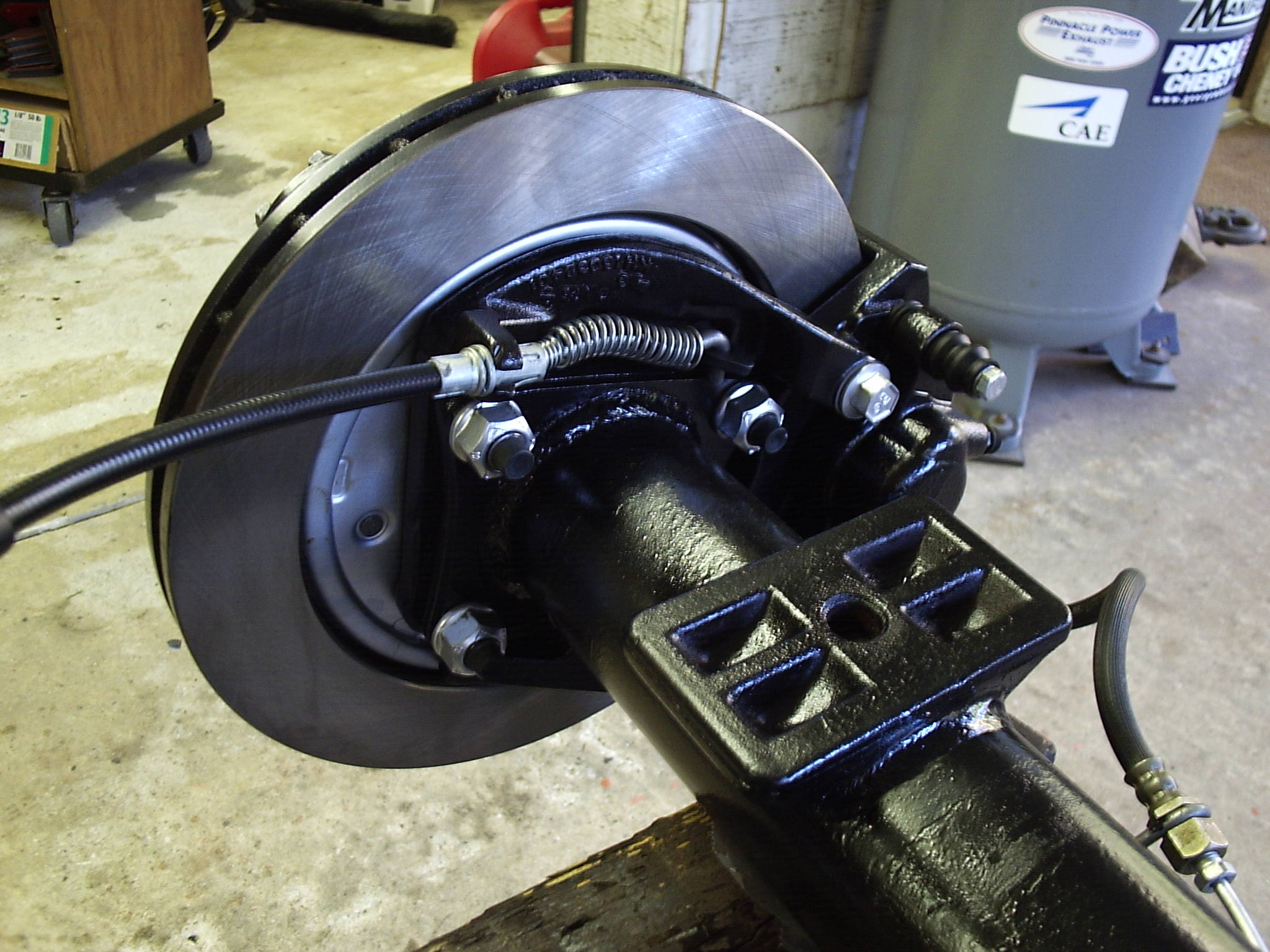
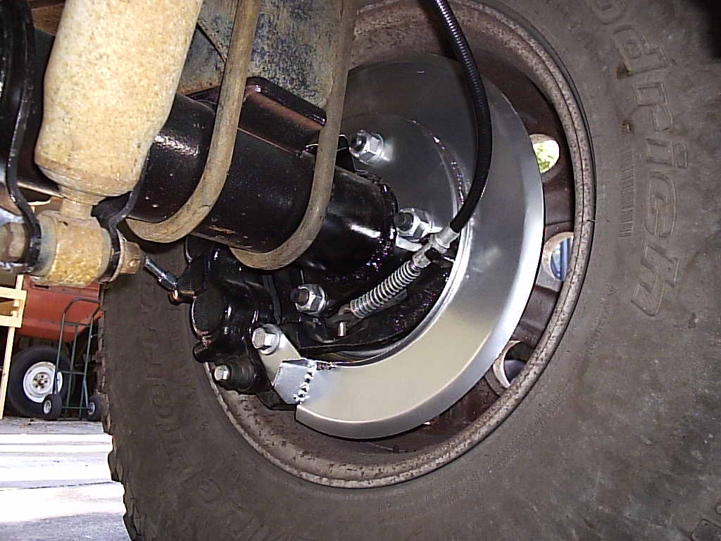
The new flange welded on looks like factory, well kinda. In the top middle pic you can see that the flanges are not oriented the same way. This is because the caliper brackets are the same, just switched around to save Kelsey Hayes some money by not manufacturing a separate left and right. With the first caliper bracket mounted up, things were starting to look good...until. Until the dang hub wouldn't mount up because it is larger in diameter than the D60 hub. A little grinding on the E-brake shoes and it fit, but without the return springs. An ACE Hardware model 111 spring was substituted for the original two return springs and things were looking good again. The ACE spring is weaker than the original two, but still has the ability to pull the shoes back inwards. See the above lower right for new spring location. Also 1/16" needed to be ground off the shoe anchor for spring clearance. Note: the new spring had to be shortened by rebending one end.
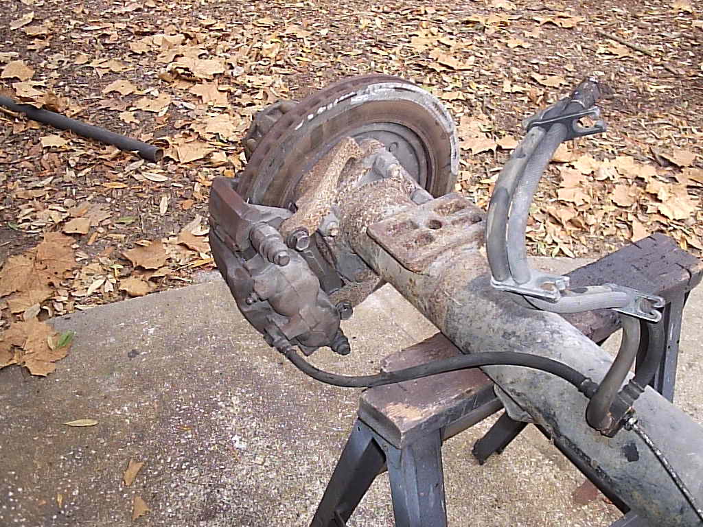
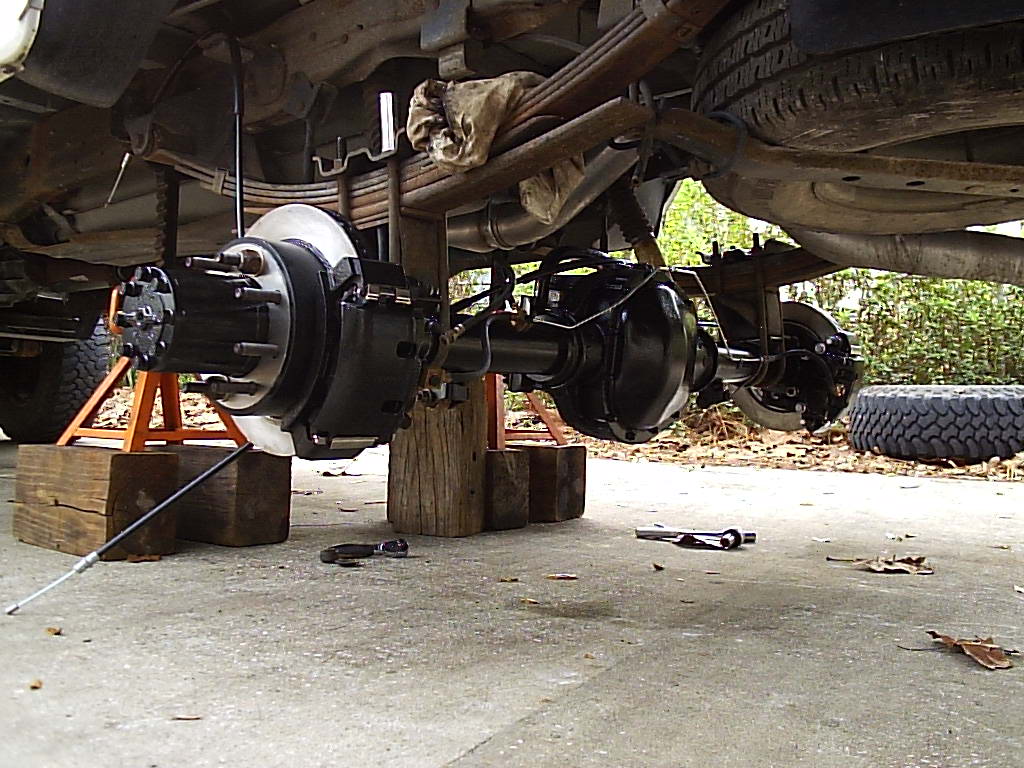
After fixing the hub clearance issue, everything else just slips back together. Also you'll note the grade 9 axle shaft bolts used. These were original to the Dana 60 axle and were far better than the original grade 8 on the Sterling.
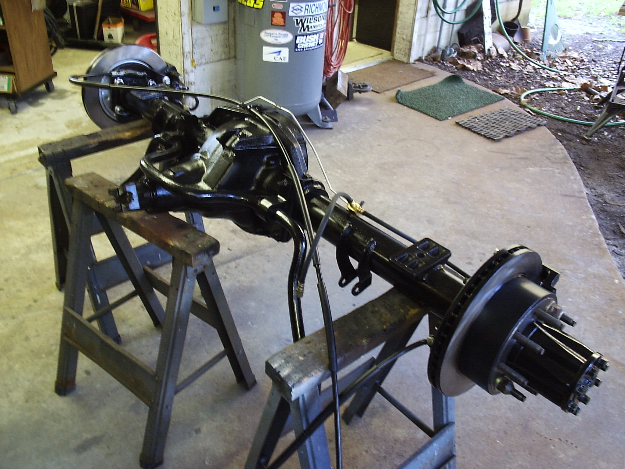
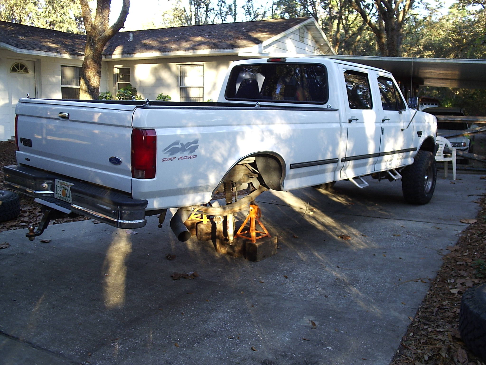
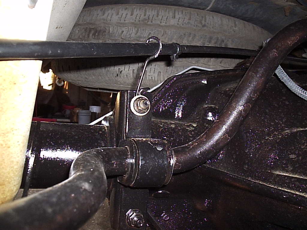
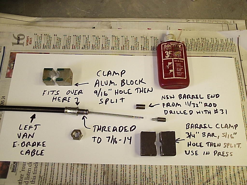
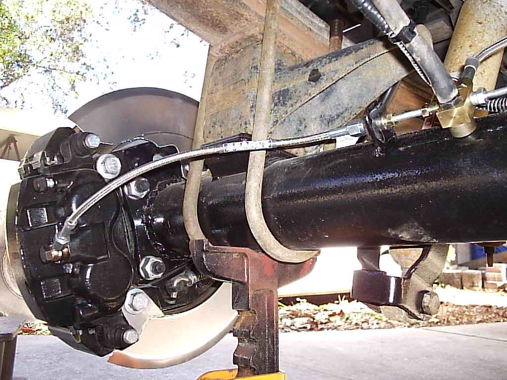
The truck sat lonely for 2 nights and on the 3rd day the axle found its home again. The brake lines from the van worked perfectly on the truck axle, except it was 3" shorter and needed a drop down bracket on the frame. We added an extra E brake cable support mounted off the sway bar mount for the right side to keep it from flopping. With the new calipers and van E-brake system we had to use the van's E-brake cables. They were a bit too short and of unequal length to hook back up to the stock equalizer bar. The solution: shorten the long one by cutting the cable and making a new barrel end. We did not actually use the method in pic 3 to below to crimp the barrel on the cable. Instead our machine shop buddies had a crimping tool. However the method in the pic will also work.
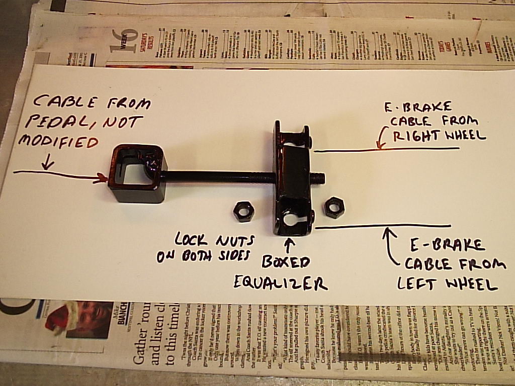
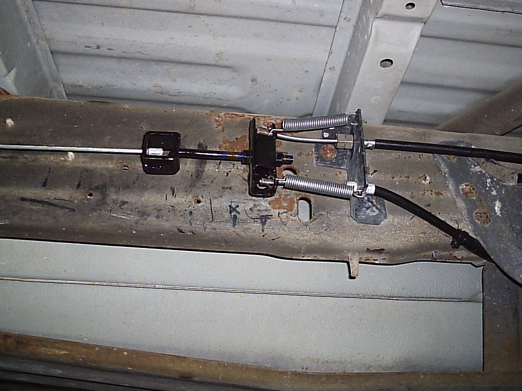
The truck's E-brake pedal has a cam inside of it to engage the cable. When there is no force on the pedal the cable is still under spring tension pulling it from the rear axle. On the original drum brakes it was not strong enough to activate the E brake, just overcome the slack. However switching to a single, weaker ACE spring in the new disc setup, we needed another set of springs to help pull the cables back to release the E brake shoes. To do this we needed a way to adjust the distance between the pedal cable and the equalizer bar. We then pulled the pedal cable taunt but not enough to move the cable and used the adjustment on the rod to take up the slack from the E brakes. To ensure the E brake cables retract when the pedal is released, we added two ACE Hardware model 118 springs between the frame bracket and equalizer bar.
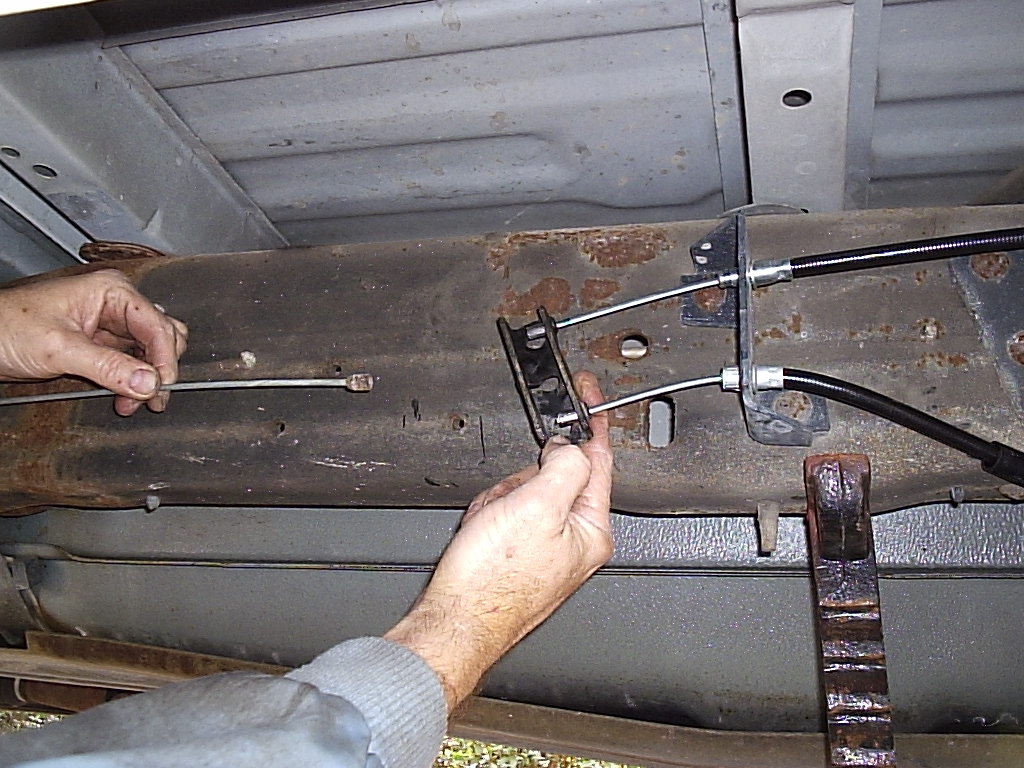
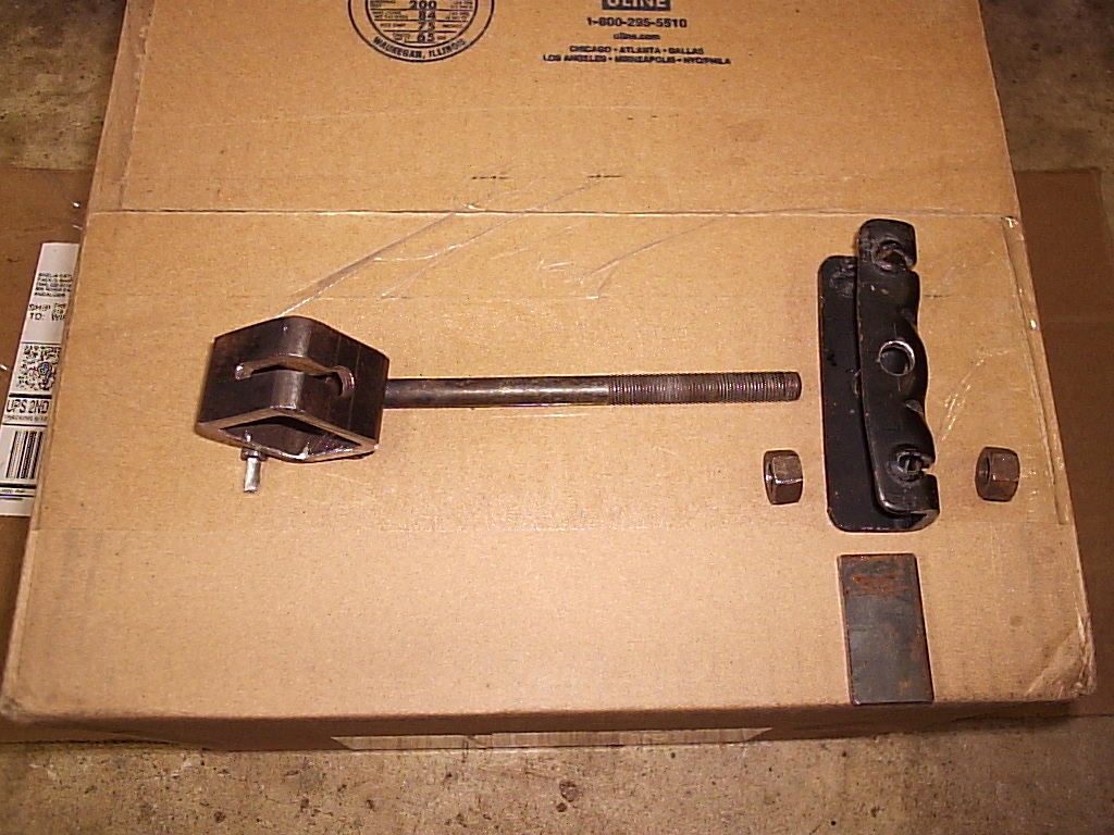
For the above two pics, we used 1-1/4" x 3/16" square tubing with a slot for the pedal cable and a 3/8" threaded rod welded together. The equalizer bar was modified by drilling a 3/8" hole through the center on each side and the tab in the lower right was used to box the center area of the equalizer bar. Pic three shows the modifications to the end of the left side cable housing. It was threaded for a 7/16"-14 nut to hold it rigid to the frame mount. The last pic shows the adjustable connection finalized.
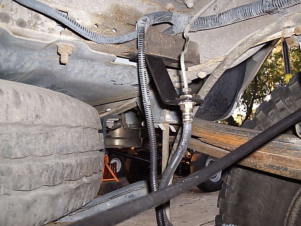
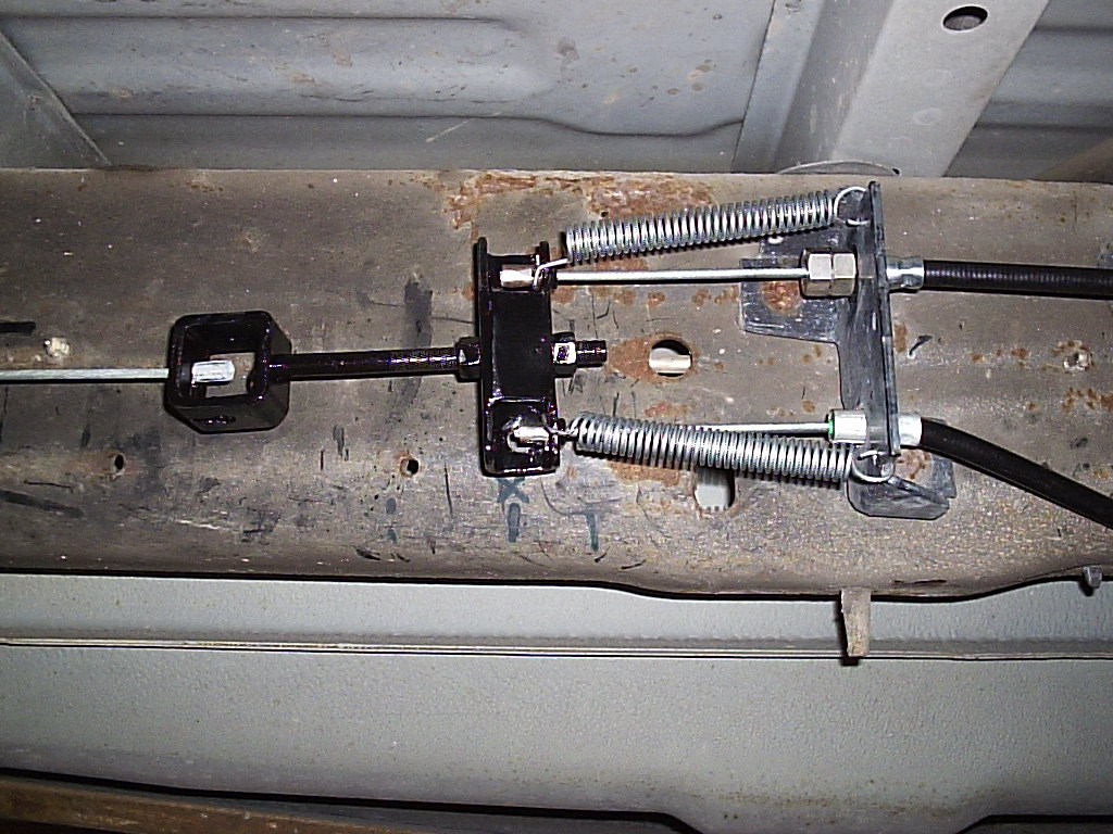
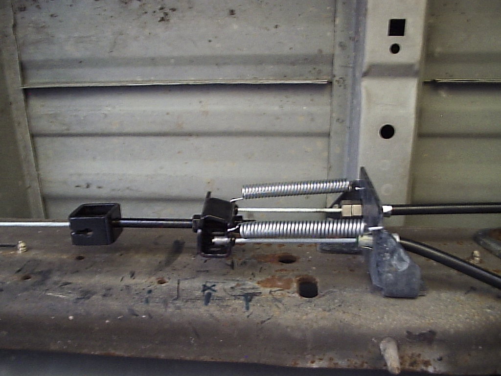
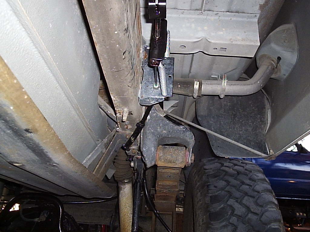
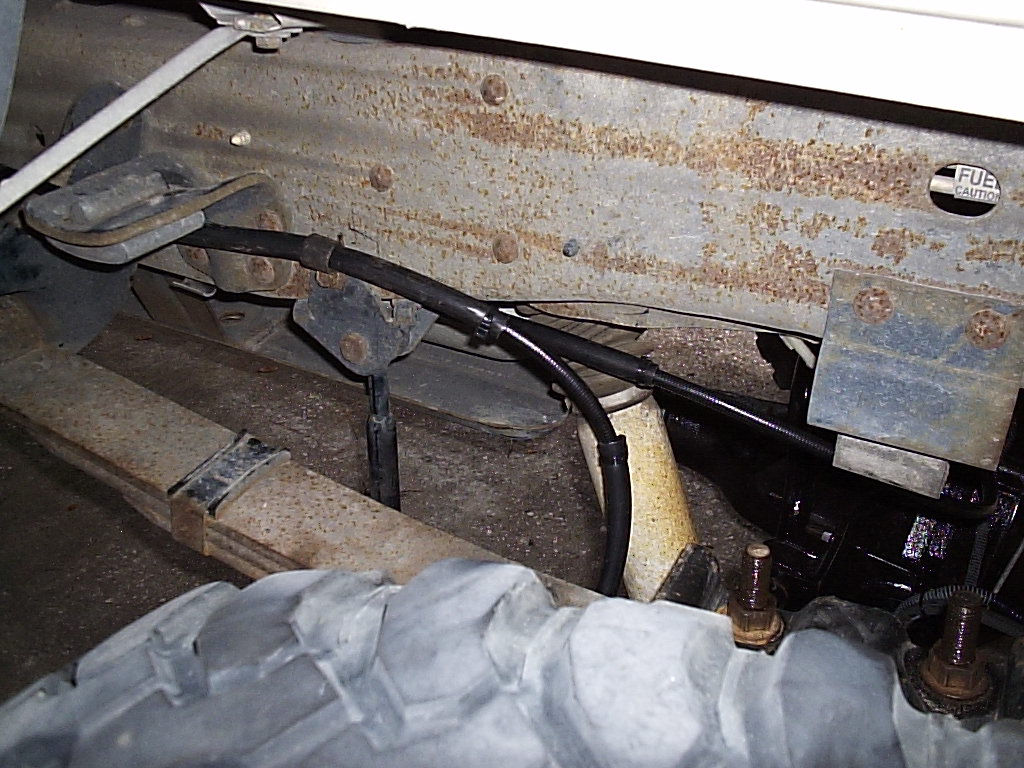
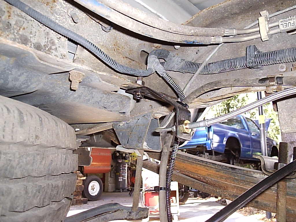
For the top row pics, the first two are under tension (E brakes applied) and the third is with brakes released. Pic 4 shows the right side cable which follows the original drum's cable routing and uses the frame rail clamp. Pic 5 shows the left side cable routed along the side of the frame and over the spring hanger, but not through it as was done originally. This keeps from having sharp bends in the cable housing. A clamp holding the housing was mounted to the side bolt of the sway bar bracket. Pic 6 shows the new pedal cable support loops to keep it from sagging.
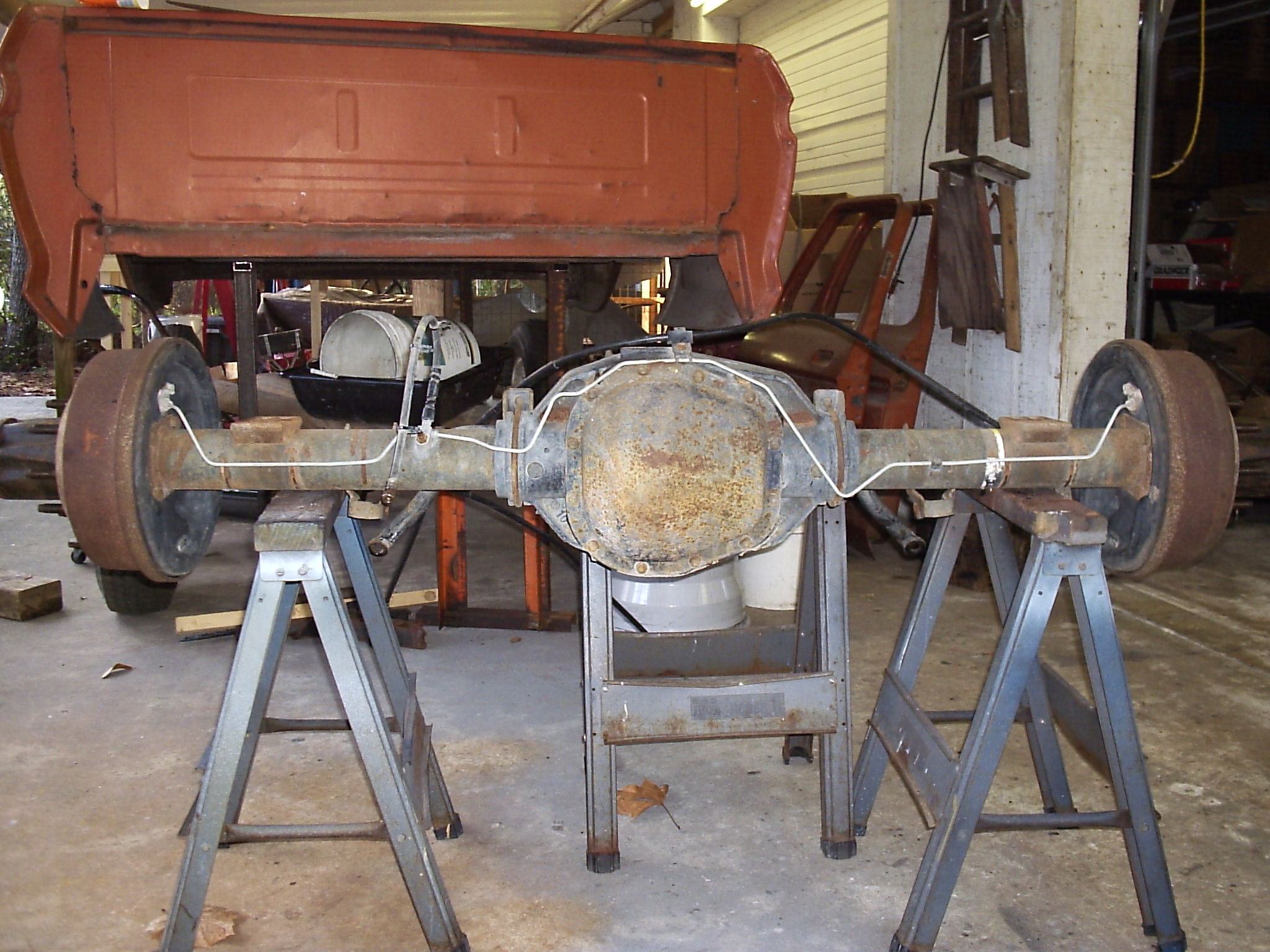
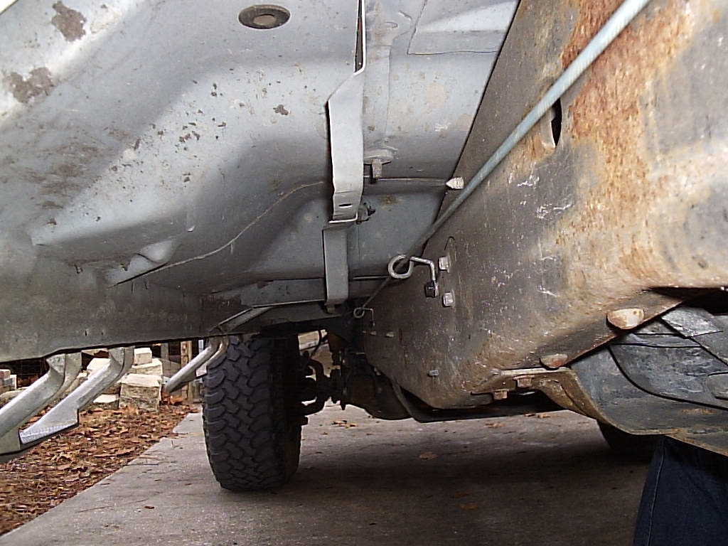
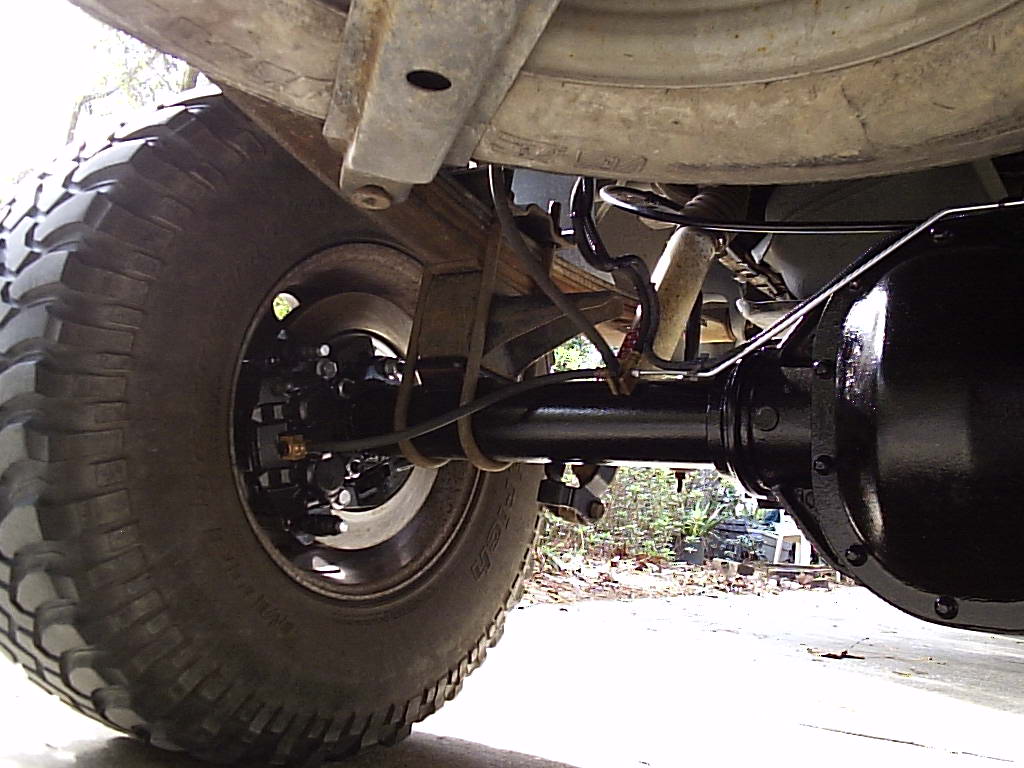
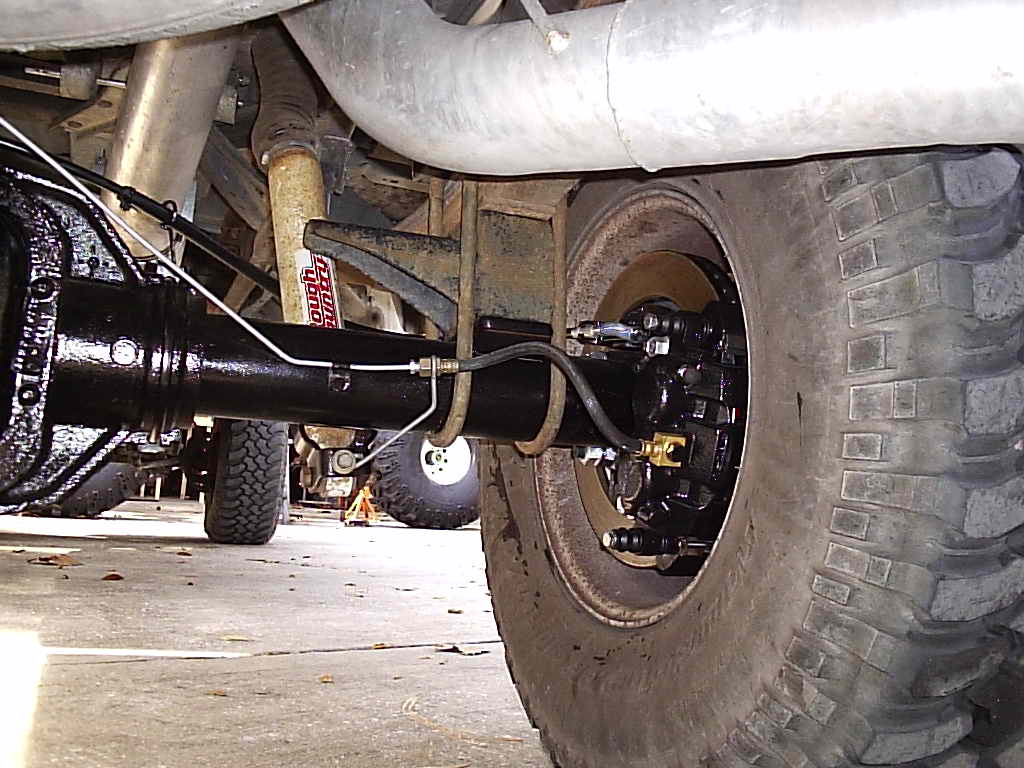
Finished photos of the rear disc conversion.
And that's it. No modifications were done to the proportioning valve or the
master cylinder. The truck has rear ABS which includes a pressure relief
accumulator in case of rear wheel lock up. It won't know the difference between
drums or discs. As for the master cylinder, we wondered if it would pump enough
volume for rear dual piston calipers so we checked with our Ford dealer. It
turns out the stock MC and the MC mounted proportioning valve are the same as
used in an
F-Superduty with rear dual piston calipers
on the Dana 80 axle and hydro
boost system.
Comments on this setup: as you can see, this is a lot of work, and is probably not a weekend job. We spent 4.5 days on the project, but we were in no rush so we took our time. You will need access to a sufficient machine shop for sure unless you have your own machining equipment. The end result was well worth it as the truck stops better than ever before.
One thing that should be addressed are the five rubber lines now instead of three. True the Super Duties have five, but the pedal feel of the '97 got a little more spongy. Nothing bad, but going to steel braided flex lines will still help the pedal feel. Another thing is the fact that newer vans and Super Duties have dust/splash shields whereas our junkyard axle did not have any. We plan on checking the Ford dealer again to see if a 1999 van had them, and if so make the purchase and install them at a later time.
Update: It turns out, the F-Superduty has a 1-5/16" master cylinder bore, while the F-350 has a 1-1/4" bore. We are not sure yet if they are interchangeable.
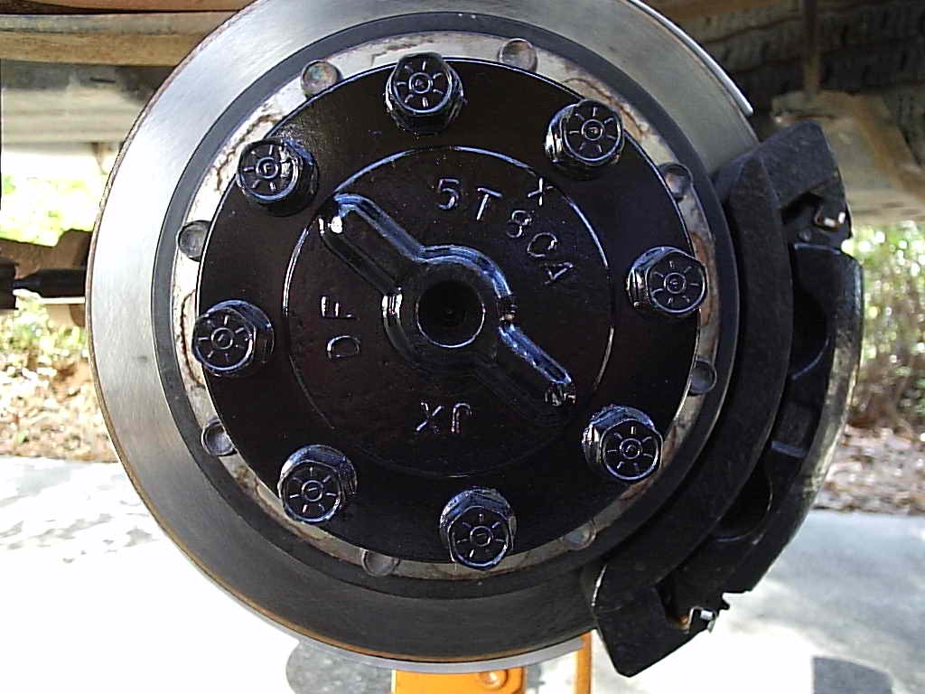
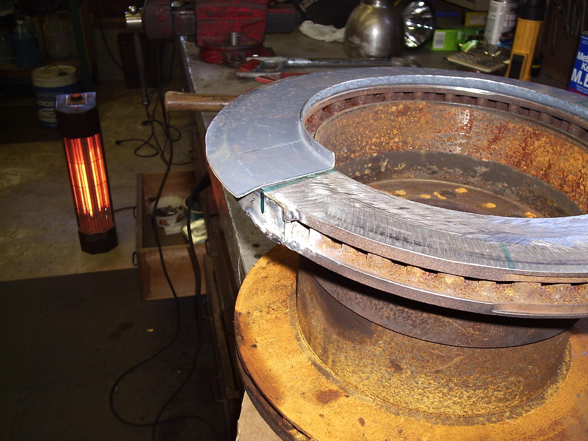
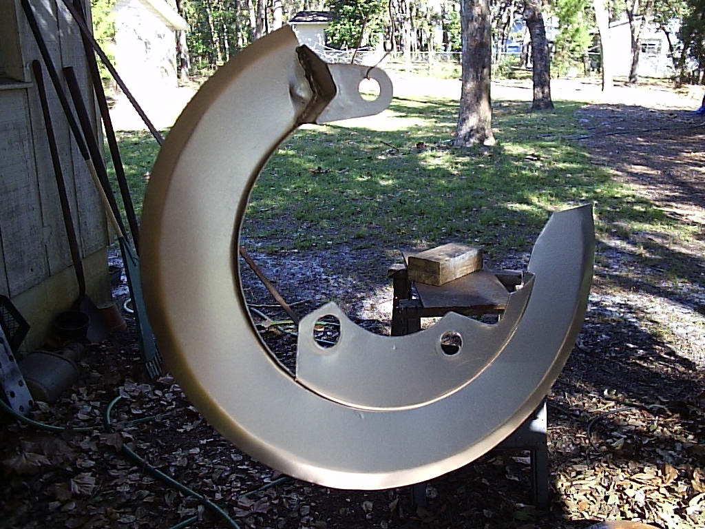
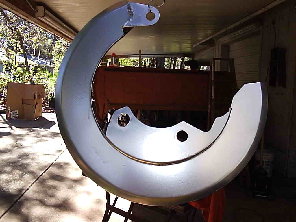
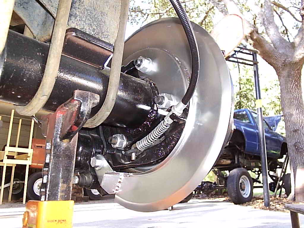
The dust/splash shields have been installed along with new Skyjacker and Earls braided stainless steel brake lines along with Russell and Aeroquip fittings. Ford does not equip the vans with full rotor shields, just a small cover for the caliper. The super duties do however come with full rotor shields. To make the truck shields work for the van, you need two of the truck's right side shields. The left side of the truck is different and will not work on the van. Unfortunately Ford does not sell them individually, but rather in a kit along with the E brake shoes and some other miscellaneous items for $198 (MSRP) per side! So again the next best thing to do is to make a set.
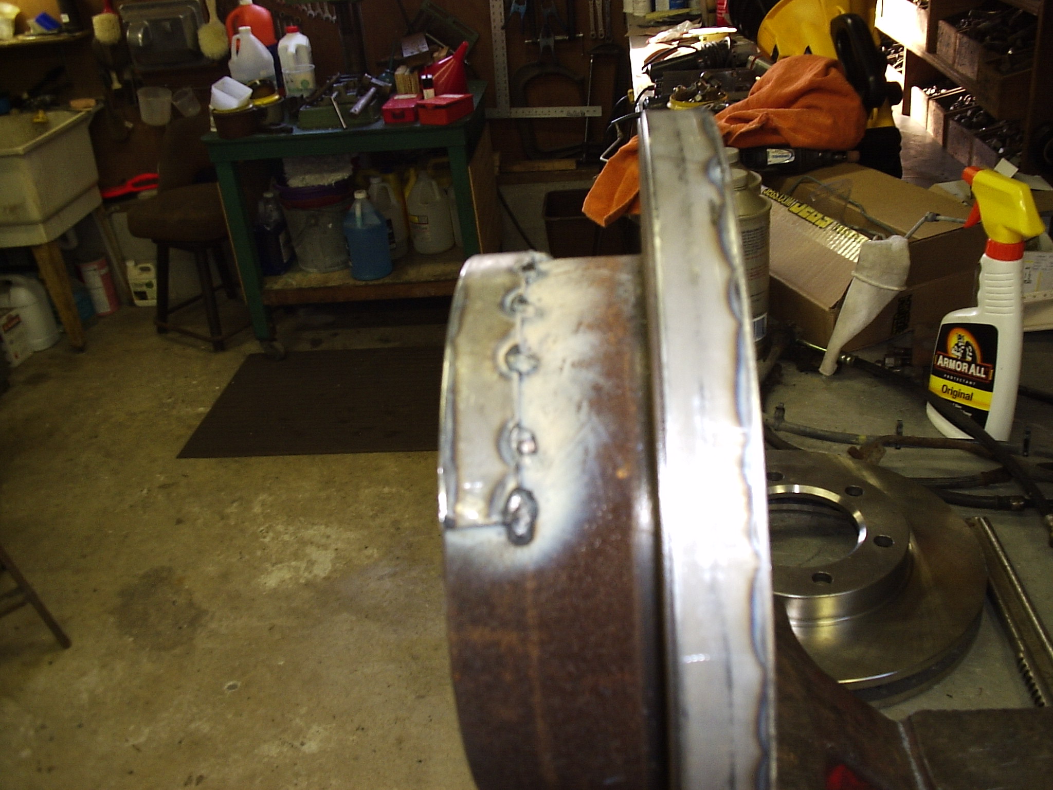
On the old rotors, we welded 1/8"x1" flat stock to the outer edge to build up the diameter for bending the shield over/around. Also the hub area was built up the same way. The shield was made from two pieces of sheet metal formed over the rotors by hand and welded together. The inner piece will mount on two of the axle flange studs and the third mount attaches to the caliper bracket bolt for a sturdy support. The offset distance of the shield to the rotor face is the same as the front Dana 60 of 1/4".
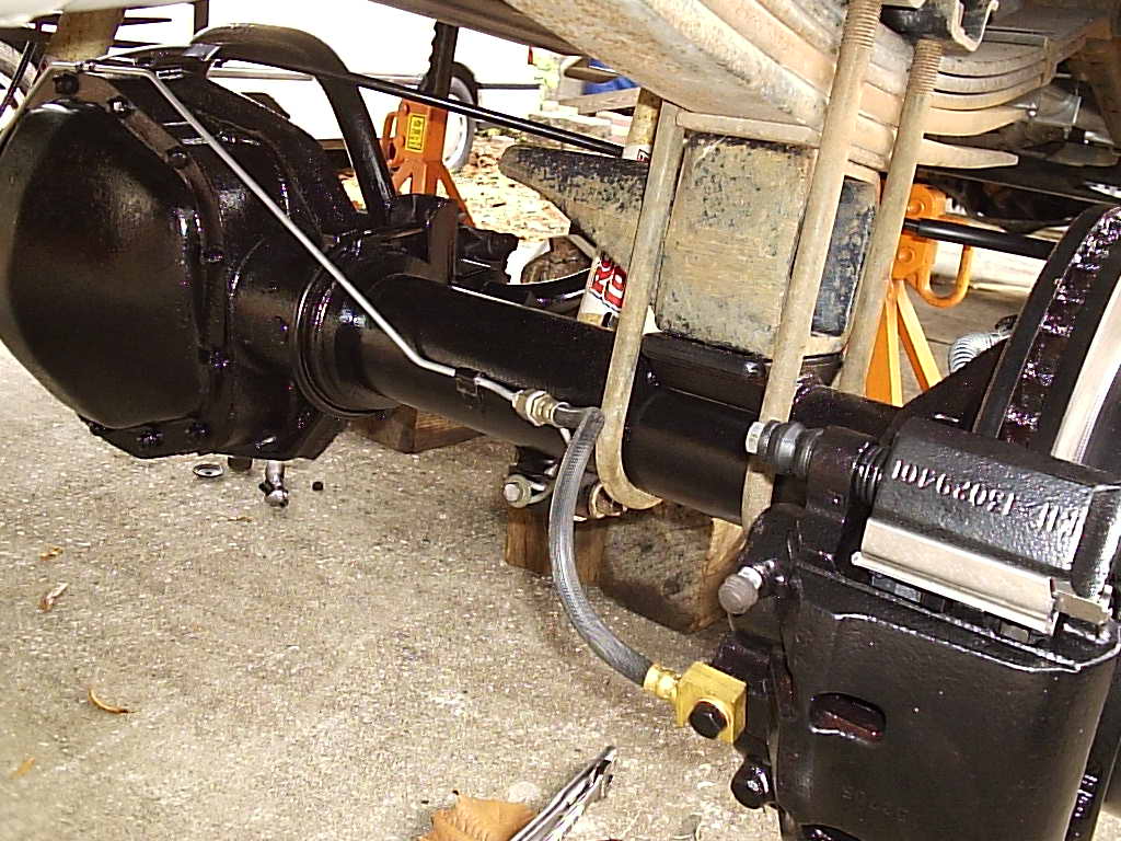
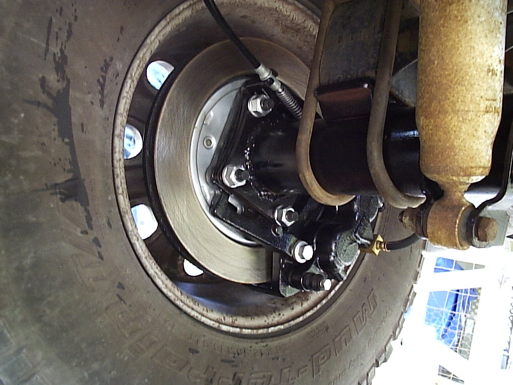
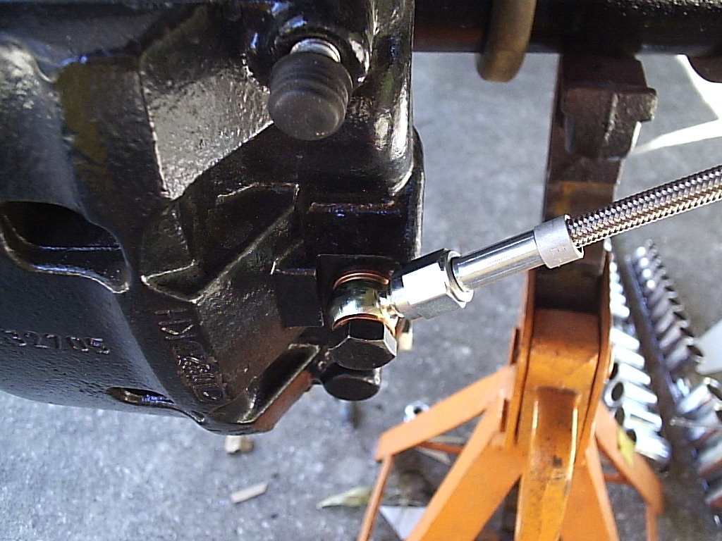
Top left shows the Aeroquip banjo fitting on the caliper and the Earls 12" braided hose. The Russell fittings were used to tie the braided lines to the hard lines. As you can see a short 3" hard line was used on the left side of the block to reach the flex line. Both hoses are 12" long. A tab was fabricated and welded on the axle tube to hold both the solid and flex lines securely. Bottom photo shows the rework of our previously fabricated drop bracket to hold the new Skyjacker flex line.
Final shots of the assembly.
Total cost: $867.05
| Axle and brakes | LKQ | 120.00 |
| 2 E brake cables | NAPA | 71.99 |
| Rotors, loaded calipers, hub seals | Advance Auto Parts | 363.44 |
| E brake shoes | PartsAmerica.com | 77.99 |
| Springs (111,118) | ACE Hardware | (6.00,8.03) |
| Earls brake hoses, Russell fittings | Jegs | 56.95 |
| Aeroquip banjo fittings | Hydraulic Supply Inc | 25.21 |
| Skyjacker front and rear flex lines | 4 Wheel Parts | 138.43 |